3.3 Wiring for CPU Unit (GT Power Supply and COM.0 Port)
3.3.1 Handling of GT Power Supply Terminals
● GT power supply terminals can be used as power supply terminals for the GT series of our
programmable displays.
● In accordance with the model to be used, use either 5V DC or 24V DC.
● GT power supply terminals (5V DC / 24V DC) are design exclusively for the GT series of our
programmable displays. Do not use the terminals for other devices.
● GT power supply terminals and COM.0 port (RS-232C) are insulated inside.
3.3.2 Terminal Layouts and Examples of Wiring
■
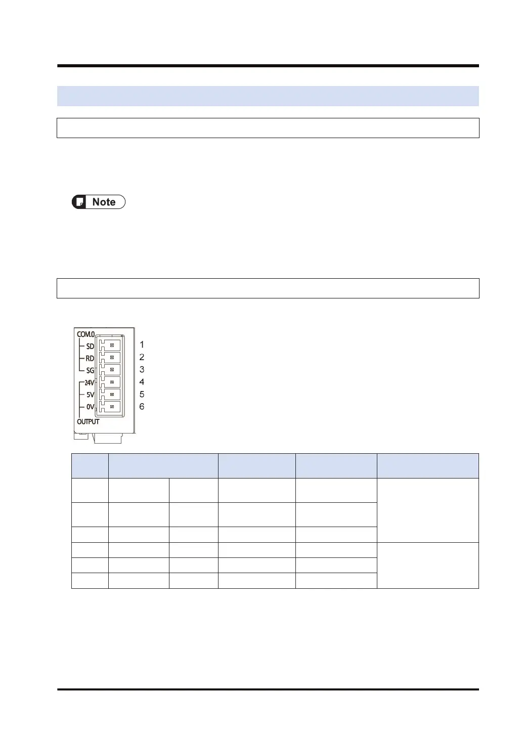
Layout for GT power supply terminals and COM.0 port terminals
Termin
al no.
Terminal part symbol
Functions that
can be allocated
Signal direction
Ports that can be
allocated in the software
1 COM.0 SD Sent data
PLC → External
device
COM.0
2 RD Received data
PLC ← External
device
3 SG Signal ground -
4 OUTPUT 24 V 24 V -
-5 5 V 5 V -
6 0 V 0 V -
3.3 Wiring for CPU Unit (GT Power Supply and COM.0 Port)
WUME-FP7COM-07 3-7

 Loading...


