Termin
al no.
LED part
symbol
Terminal
part symbol
Functions that
can be allocated
Signal direction
Ports that can be
allocated in the software
8 485
+ / R Received Data
(+)
PLC ← External
device
9 422
- / R
Received Data (-)
PLC ← External
device
(Note 1) Do not connect anything to Terminal No.5.
(Note 2) The route between CH1 and CH2 is insulated inside.
■
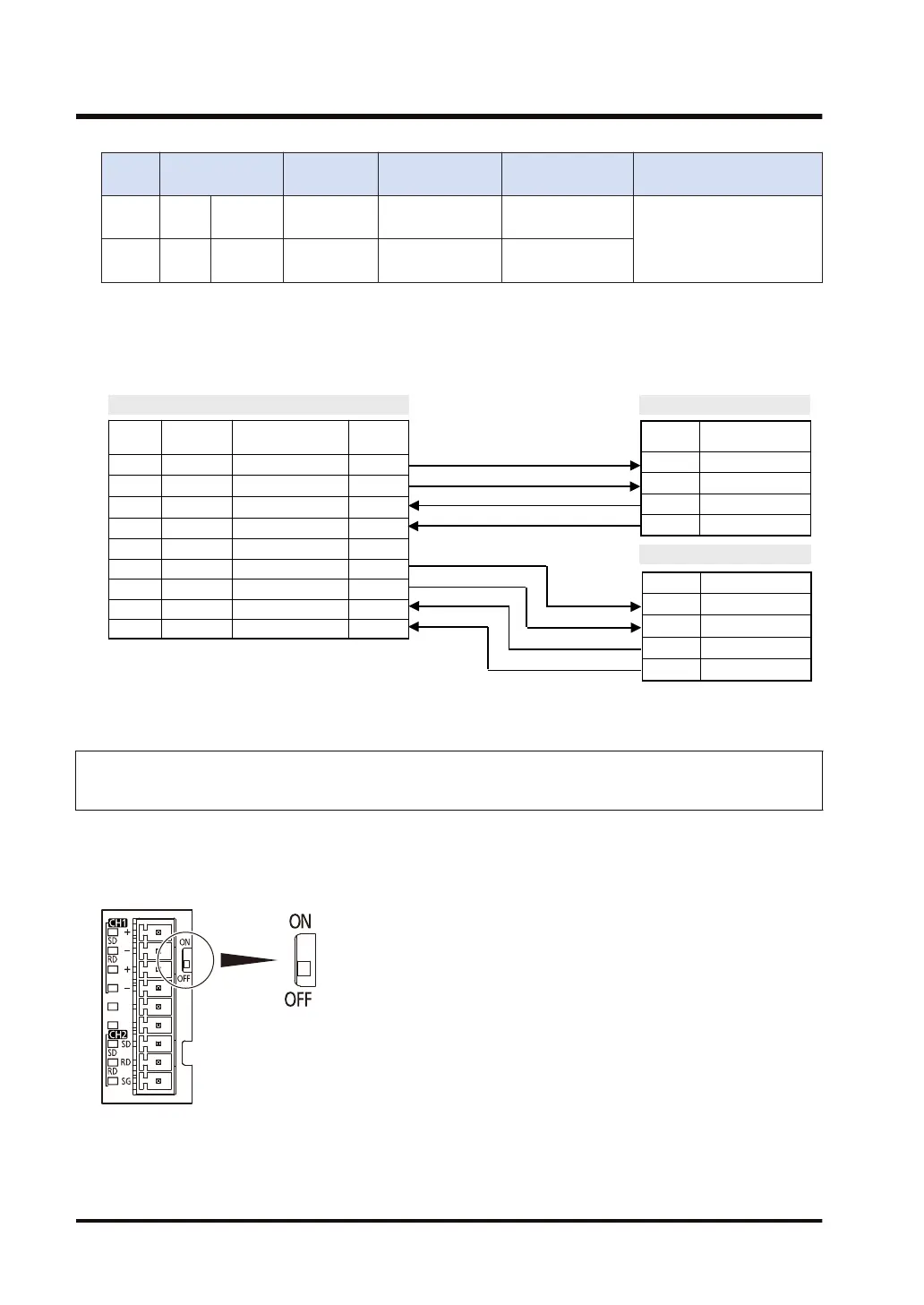
Example of wiring (in the setting of RS-422)
AFP7CCRM2
Terminal
No.
Terminal
part symbol
Signal name Functions
1 + / S Sent Data 1 (+) SD (+)
2 - / S Sent Data 1 (-) SD (-)
3 + / R Received Data 1 (+) RD (+)
4 - / R Received Data 1 (-) RD (-)
5 -
6 + / S Sent Data 2 (+) SD (+)
7 - / S Sent Data 2 (-) SD (-)
8 + / R Received Data 2 (+) RD (+)
9 - / R Received Data 2 (-) RD (-)
Partner 1
Partner 2
Terminal Signal name
RD (+) Received Data (+)
RD (-) Received Data (-)
SD (+) Sent Data (+)
SD (-) Sent Data (-)
Terminal Signal name
RD (+) Received Data (+)
RD (-) Received Data (-)
SD (+) Sent Data (+)
SD (-) Sent Data (-)
3.4.5 Communication Cassette AFP7CCRS1M1 (RS-232C 1-Channel + RS-485
1-Channel Insulated Type)
■
Settings for termination resistance selector switch
A termination resistance selector switch is located on the RS-485 side of the surface of
Communication Cassette AFP7CCRS1M1. Turn ON the switch only when it is the end unit.
3.4 Wiring for Communication Cassettes COM.1 to COM.4 Ports
3-18 WUME-FP7COM-07

 Loading...


