■
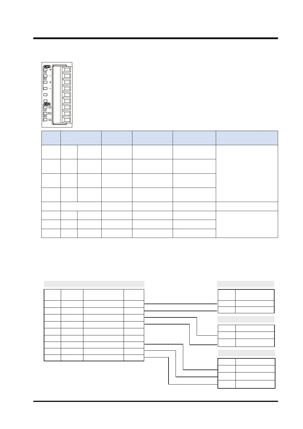
Terminal layout
Termin
al no.
LED part
symbol
Terminal
part symbol
Functions that
can be allocated
Signal direction
Ports that can be
allocated in the software
1 CH1 SD +
Transmission line
(+)
-
COM.1/COM.3
2 RD
- Transmission line
(-)
-
3
+ Transmission line
(+)
-
4
- Transmission line
(-)
-
5 to 6 - - - - -
7 CH2 SD SD Sent data -
COM.2/COM.4
8 RD RD Received data -
9 SG SG Signal ground -
(Note 1) Terminal No.1 and Terminal No.3, and Terminal No.2 and Terminal No.4 are respectively connected
inside.
(Note 2) Do not connect anything to Terminals No.5 and No.6.
■
Example of wiring
AFP7CCRS1M1
Termina
l No.
Terminal
part symbol
Signal name Functions
1 + / S Transmission line (+) +
2 - / S Transmission line (-) -
3 + / R Transmission line (+) +
4 - / R Transmission line (-) -
5 - NC NC
6 - NC NC
7 SD Sent Data SD
8 RD Received Data RD
9 SG Signal Ground SG
RS-485 Partner 1
Terminal Signal name
+ Transmission line (+)
- Transmission line (-)
RS-485 Partner 2
RS-232C partner
Terminal Signal name
+ Transmission line (+)
- Transmission line (-)
Terminal Signal name
RD Received Data
SD Sent Data
SG Signal Ground
3.4 Wiring for Communication Cassettes COM.1 to COM.4 Ports
WUME-FP7COM-07 3-19

 Loading...


