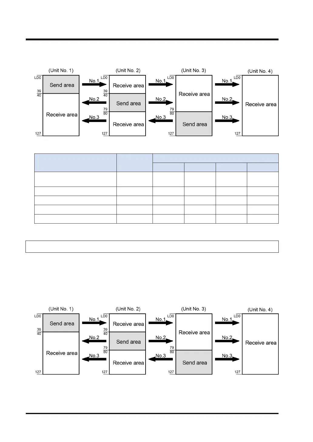
Example) Setting of the link relay transmission start number and sending size (in the
case of memory block No. 0)
■
List of setting items (for PLC link setting)
Setting item Setting range
Unit No. and setting method
No.1 No.2 No.3 No.4
Memory block No. of link relays and
link registers to be used
0 or 1 0 0 0 0
Max. unit No. used for PLC link 0 to 16 4 4 4 4
Range of link relays used 0 to 64 words 64 64 64 64
Transmission start No. for link relays 0 to 63 0 20 40 0
Size of link relay send area 0 to 64 words 20 20 24 0
6.3.6 Link Register Transmission Start Number and Sending Size
● The memory areas of link registers are divided into send areas and receive areas.
● Link registers are transmitted from the send area of a PLC to the receive area of another
PLC. The receiving PLC must have the same link register No. in its receive area as the
sending PLC.
Example) Setting of the link register transmission start number and sending size (in
the case of memory block No. 0)
6.3 Setting Items for PLC Link
6-10 WUME-FP7COM-07

 Loading...


