EasyManua.ls Logo

Panasonic FP7 Series User Manual

Panasonic FP7 Series
192 pages
To Next Page IconTo Next Page
To Previous Page IconTo Previous Page
Page #154 background imageLoading...
Page #154 background image
9.4.2 Contents of Received Data
When data are copied into a given data register, based on GPRECV instruction, the data are
saved in the following manner.
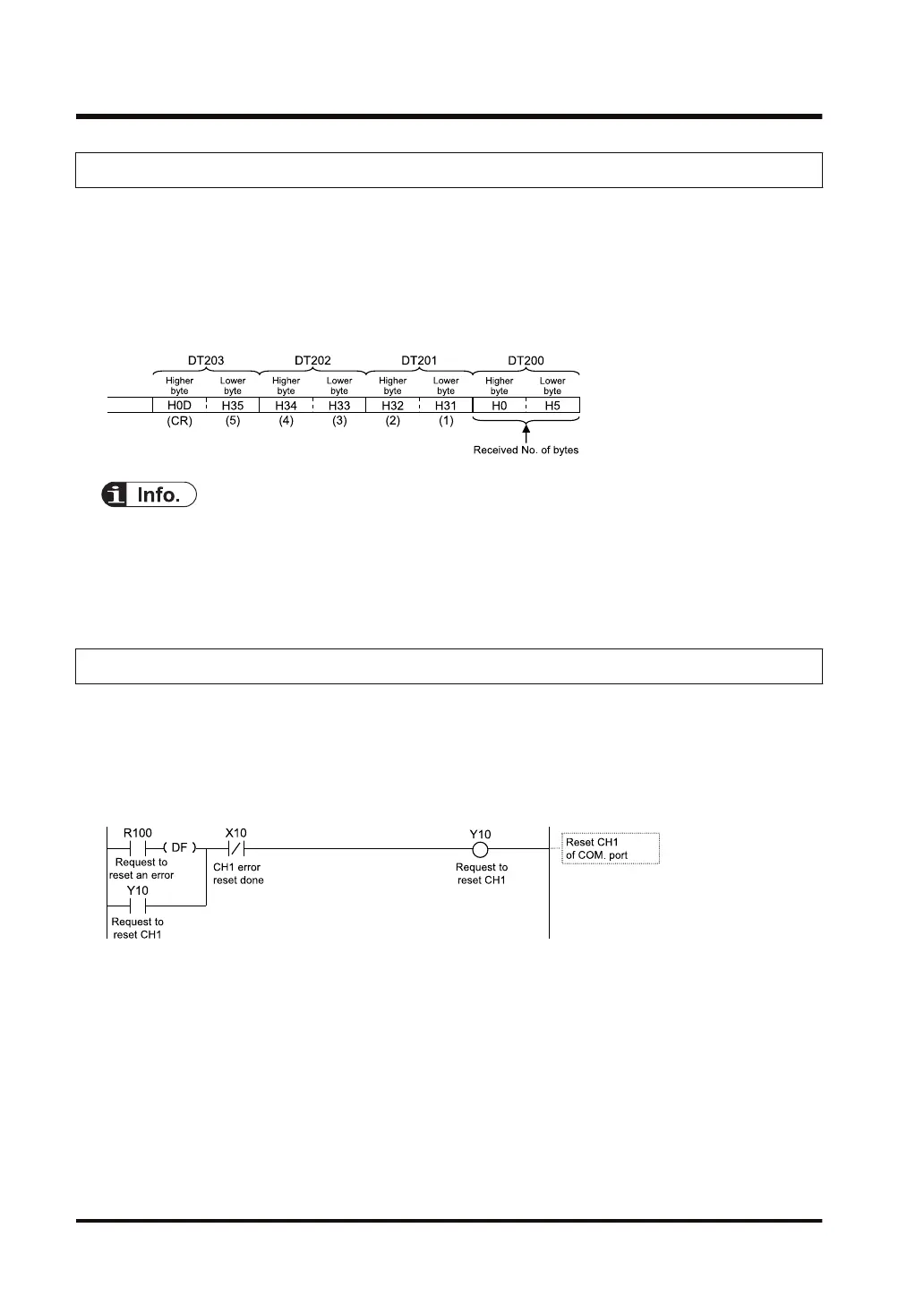
Example: The data “12345 CR” is transmitted from a device with RS-232C device.
At the beginning of the data register, the No. of received bytes is saved.
The received data are saved in ascending order from lower bytes to higher bytes, starting
with DT201.
The received data that are copied based on the GPRECV instruction do not include a start
code or end code.
It is also possible to receive binary data based on the GPRECV instruction. In this case, the
terminator should be specified using "Time".
9.4.3 Precautions on Receiving Data
Reset communication ports
If a communication abnormality has occurred, communication ports can be reset by turning
on the "Request to reset" signal (Y10, Y11, Y12, Y13) by the user program.
Once reset is completed, (X10, X11, X12, X13) turns ON. Subsequently, turn OFF the
"Request to reset" (Y10, Y11, Y12, Y13).
Procedure for repeated reception of data
For repeated reception of data, perform the following steps 1 to 4:
1. Receive data.
2. Turn on the "General-purpose communication reception done" flag (X0, X1, X2, X3).
3. Specify a port to receive data based on the UNITSEL instruction.
4. Execute the GPRECV instruction and read the received data from the reception buffer.
9.4 Receiving Operation
9-20 WUME-FP7COM-07

Table of Contents

Other manuals for Panasonic FP7 Series

Question and Answer IconNeed help?

Do you have a question about the Panasonic FP7 Series and is the answer not in the manual?

Panasonic FP7 Series Specifications

General IconGeneral
CPU32-bit RISC
Program MemoryFlash ROM
Programming LanguageLadder
Communication PortsRS-232, RS-485, Ethernet
Operating Temperature0 to +55°C
Power Supply24V DC

Summary

Safety Precautions

Handling Precautions

Outlines safety symbols and important precautions for handling the product.

Unit Functions and Restrictions on Combination

Features and Functions of Units

Describes the capabilities and communication modes of FP7 units.

Overview of Communication Functions

Summarizes PLC Link, MEWTOCOL, MODBUS RTU, and general-purpose communication.

Wiring the COM. Port

Wiring of COM. Port Terminal Block

Explains suitable wires, tools, and methods for wiring terminal blocks.

Wiring for Communication Cassettes COM.1 to COM.4 Ports

Provides wiring diagrams and details for various communication cassettes.

I/O Allocation

Input/Output Signals Used for Communication

Maps I/O signals to communication ports for CPU and serial units.

Setting and Confirming Communication Conditions

Setting Applications and Communication Conditions

Details available functions for each communication port and general settings.

Setting Communication Conditions

Explains how to configure communication parameters using FPWIN GR7.

PLC Link

Configuration Required for PLC Link

Details the setup procedure and setting items for PLC Link configuration.

Setting Items for PLC Link

Lists and explains parameters for PLC Link configuration.

MEWTOCOL Master-Slave Communication

MODBUS RTU Master-Slave Communication

General-Purpose Communication

Troubleshooting

Self-diagnostic Function

Describes LED indications on the CPU and serial units for self-diagnosis.

What to Do If an Error Occurs (For Each Communication Mode)

Provides troubleshooting steps for errors in various communication modes.

Related product manuals