3.4 Wiring for Communication Cassettes COM.1 to COM.4 Ports
3.4.1 Communication Cassette AFP7CCRS1 (RS-232C, 1-Channel Insulated
Type)
■
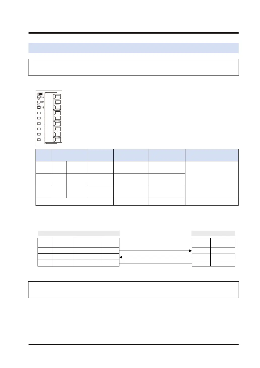
Terminal layout
Termin
al no.
LED part
symbol
Terminal
part symbol
Functions that
can be allocated
Signal direction
Ports that can be
allocated in the software
1 CH1 SD SD SD: Sent Data
PLC → External
device
COM.1/COM.32 RD RD
RD: Received
Data
PLC ← External
device
3 - SG
SG: Signal
Ground
-
4 to 9 - - - - -
(Note 1) Do not connect anything to Terminals No.4 through No.9.
■
Example of wiring
AFP7CCRS1
Terminal
No.
Terminal
part symbol
Signal name Functions
1 SD Sent Data 1 SD
2 RD Received Data 1 RD
3 SG Signal Ground SG
Partner
Symbol Signal name
RD Received Data
SD Sent Data
SG Signal Ground
3.4.2 Communication Cassette AFP7CCRS2 (RS-232C, 2-Channel Insulated
Type)
■
Setting of application switch
Applications for use can be switched using a switch on the backplane for Communication
Cassette AFP7CCRS2. Settings can be confirmed with "3Wire" or "5Wire" LED lamp lit on the
front of the cassette.
3-wire 2-channel RS-232C
3.4 Wiring for Communication Cassettes COM.1 to COM.4 Ports
WUME-FP7COM-07 3-9

 Loading...


