5-wire 1-channel RS-232C (RS/CS controlled)
(Note 1) The switch is factory-set to 3Wire (3-wire 2-channel RS-232C).
■
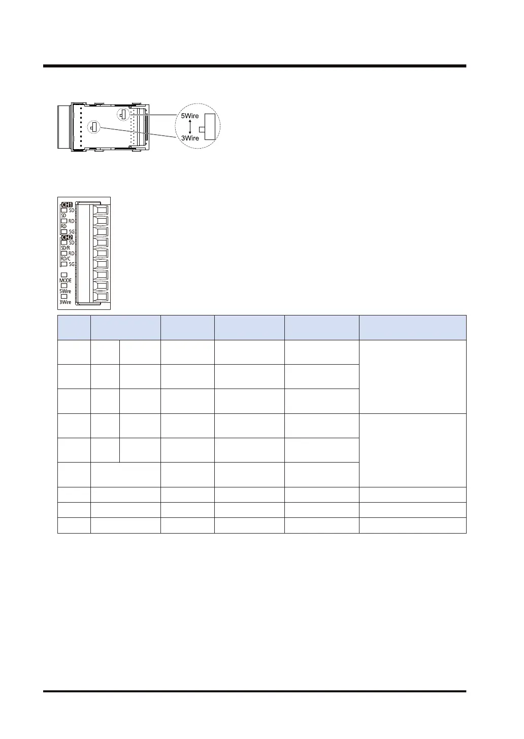
Terminal layout (in the setting of 3-wire 2-channel RS-232C)
Termin
al no.
LED part
symbol
Terminal
part symbol
Functions that
can be allocated
Signal direction
Port that can be allocated
in the software
1 CH1 SD SD SD: Sent Data
PLC → External
device
COM.1/COM.32 RD RD
RD: Received
Data
PLC ← External
device
3 - SG
SG: Signal
Ground
-
4 CH2 SD / R SD SD: Sent Data
PLC → External
device
COM.2/COM.45 RD / C RD
RD: Received
Data
PLC ← External
device
6 - SG
SG: Signal
Ground
-
7 MODE - - - -
8 3-Wire - - - -
9 5-Wire - - - -
(Note 1) The route between CH1 and CH2 is insulated inside.
(Note 2) Do not connect anything to Terminals No.7 through No.9.
3.4 Wiring for Communication Cassettes COM.1 to COM.4 Ports
3-10 WUME-FP7COM-07

 Loading...


