■
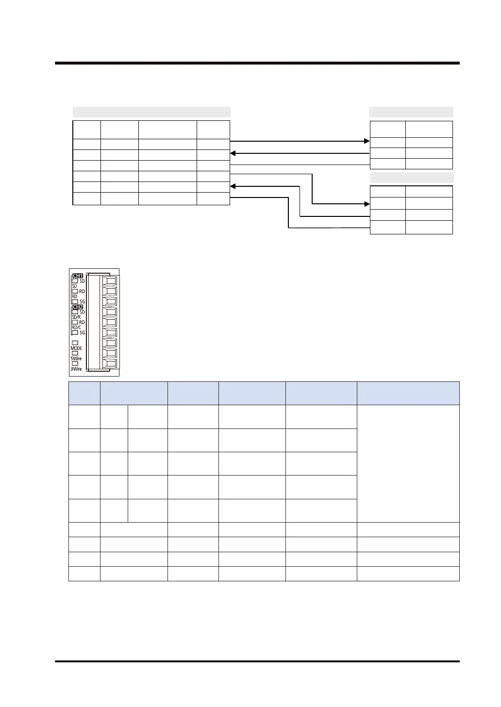
Example of wiring (in the setting of 3-wire 2-channel RS-232C)
AFP7CCRS2
Termina
l No.
Terminal
part symbol
Signal name Functions
1 SD Sent Data 1 SD
2 RD Received Data 1 RD
3 SG Signal Ground SG
4 SD Sent Data 2 SD
5 RD Received Data 2 RD
6 SG Signal Ground SG
Symbol Signal name
RD Received Data
SD Sent Data
SG Signal Ground
Symbol Signal name
RD Received Data
SD Sent Data
SG Signal Ground
Partner 1
Partner 2
■
Terminal layout (in the setting of 5-wire 1-channel RS-232C RS/CS controlled)
Termin
al no.
LED part
symbol
Terminal
part symbol
Functions that
can be allocated
Signal direction
Ports that can be
allocated in the software
1 CH1 SD SD SD: Sent Data
PLC → External
device
COM.1/COM.3
2 RD RD
RD: Received
Data
PLC ← External
device
3 - SG
SG: Signal
Ground
-
4 CH2 SD / R SD
RS: Request to
Send
PLC → External
device
5 RD / C RD
CS: Clear to
Send
PLC ← External
device
6 - SG - - -
7 MODE - - - -
8 3-Wire - - - -
9 5-Wire - - - -
(Note 1) Do not connect anything to Terminals No.6 through No.9.
3.4 Wiring for Communication Cassettes COM.1 to COM.4 Ports
WUME-FP7COM-07 3-11

 Loading...


