■
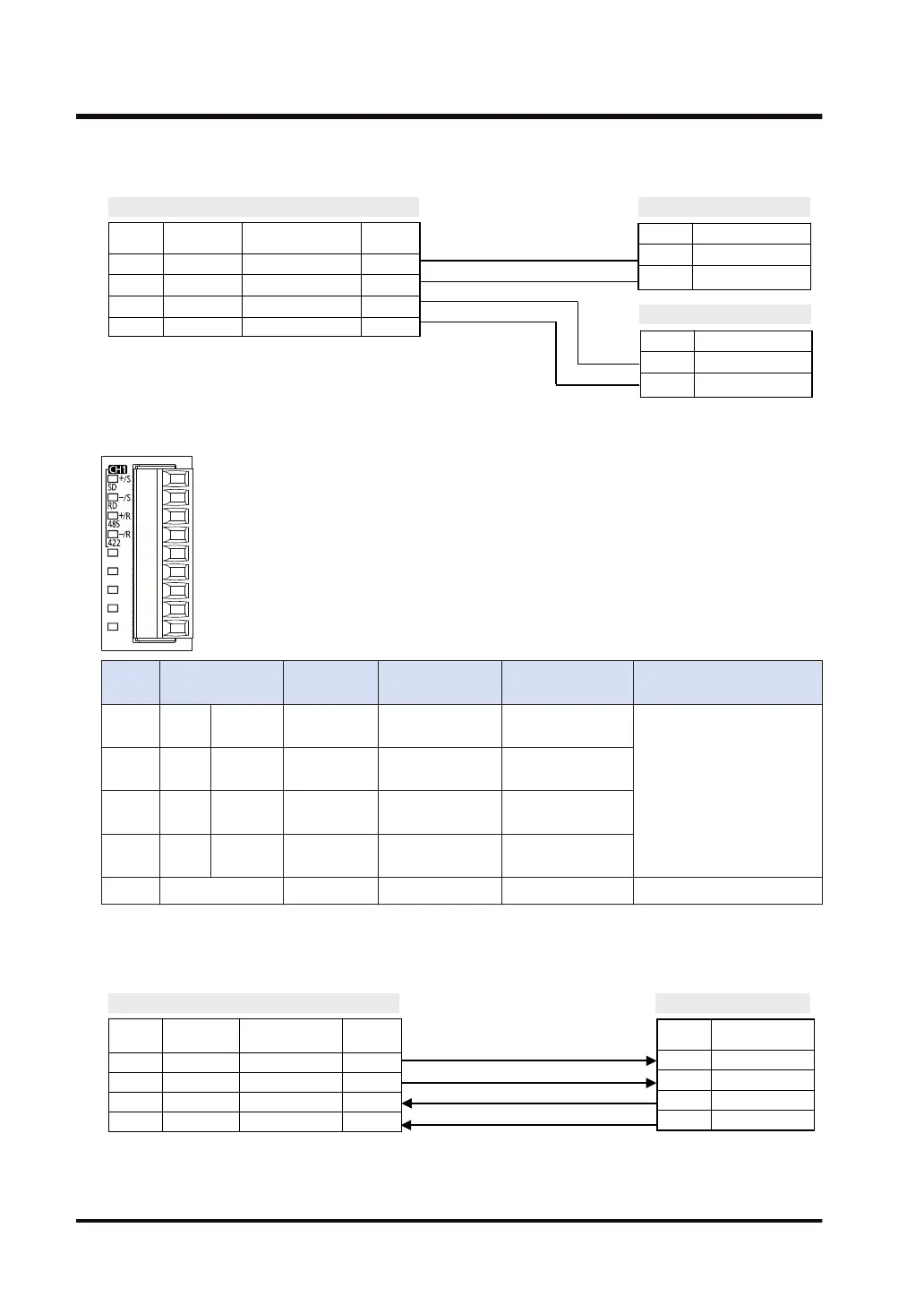
Example of wiring (in the setting of RS-485)
AFP7CCRM1
Terminal
No.
Terminal part
symbol
Signal name Functions
1 + / S Transmission line (+) +
2 - / S Transmission line (-) -
3 + / R Transmission line (+) +
4 - / R Transmission line (-) -
Terminal Signal name
+ Transmission line (+)
- Transmission line (-)
Terminal Signal name
+ Transmission line (+)
- Transmission line (-)
Partner 1
Partner 2
■
Terminal layout (in the setting of RS-422)
Termin
al no.
LED part
symbol
Terminal
part symbol
Functions that
can be allocated
Signal direction
Ports that can be
allocated in the software
1 CH1 SD + / S Sent Data (+)
PLC → External
device
COM.1/COM.3
2 RD
- / S
Sent Data (-)
PLC → External
device
3 485
+ / R Received Data
(+)
PLC ← External
device
4 422
- / R
Received Data (-)
PLC ← External
device
5 to 9 - - - - -
(Note 1) Do not connect anything to Terminals No.5 through No.9.
■
Example of wiring (in the setting of RS-422)
AFP7CCRM1
Terminal
No.
Terminal part
symbol
Signal name Functions
1 + / S Sent Data (+) SD (+)
2 - / S Sent Data (-) SD (-)
3 + / R Received Data (+) RD (+)
4 - / R Received Data (-) RD (-)
Partner
Terminal Signal name
RD (+) Received Data (+)
RD (-) Received Data (-)
SD (+) Sent Data (+)
SD (-) Sent Data (-)
3.4 Wiring for Communication Cassettes COM.1 to COM.4 Ports
3-14 WUME-FP7COM-07

 Loading...


