Home
Panasonic
Controller
FP7 Series
Panasonic FP7 Series User Manual
4
of 1
of 1 rating
192 pages
Give review
Manual
Specs
To Next Page
To Next Page
To Previous Page
To Previous Page
Loading...
5.
Double-click Slot No. 1 in the "I/O map" dialog box.
The "Unit selection [Slot No. 1]" dialog box is displayed.
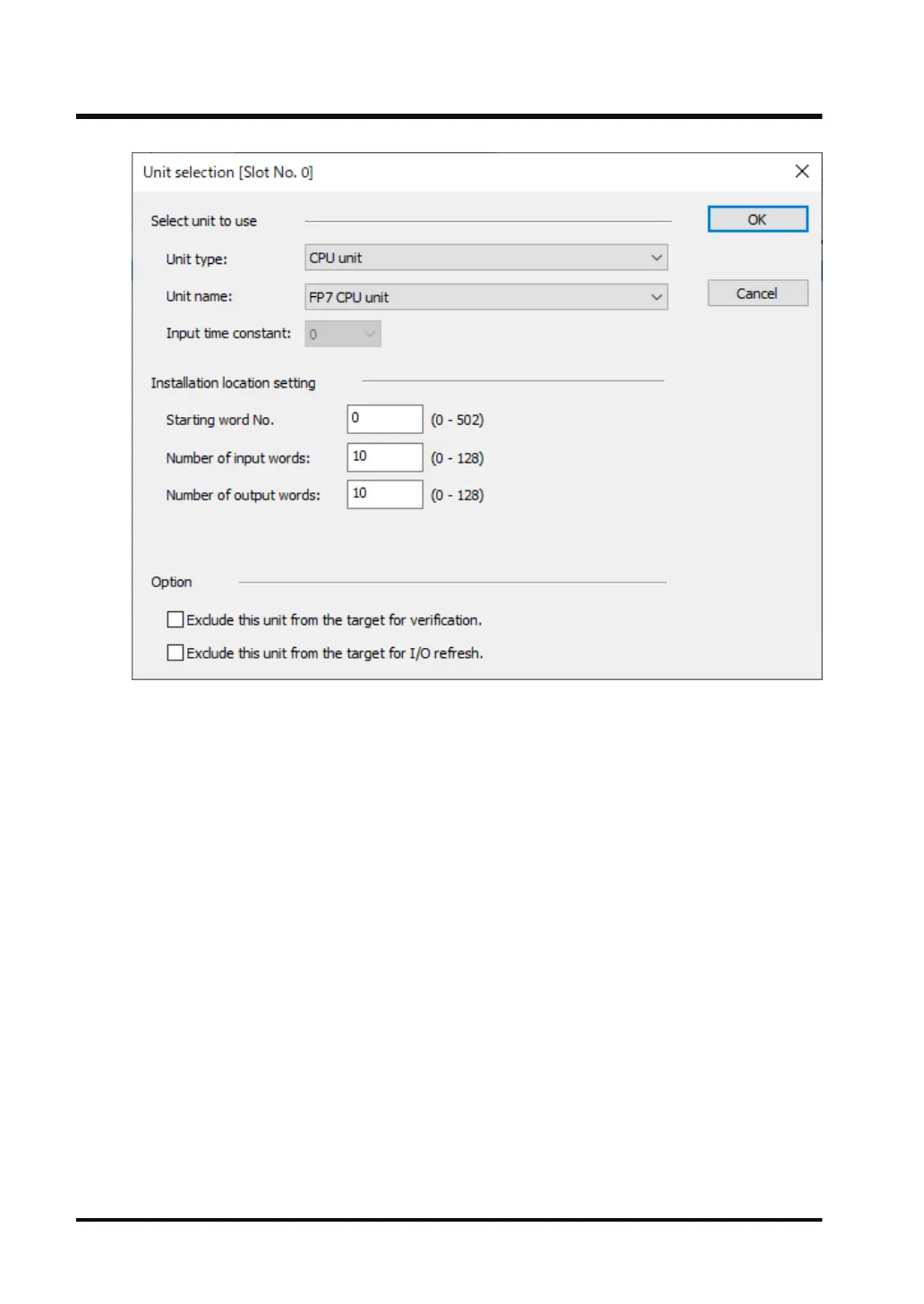
6.
Select "Communications" for Unit type, select "SCU unit" for Unit name, and press the [OK]
button.
"SCU unit" is registered in the I/O map.
4.2 Registration in I/O Map
4-8
WUME-FP7COM-07
51
53
Table of Contents
Table of Contents
7
Unit Functions and Restrictions on Combination
11
Features and Functions of Units
12
Functions of Units
12
Unit Type
13
Types of Cassette
13
Applications that Can be Used in each Port
13
Overview of Communication Functions
15
PLC Link Functions (MEWNET-W0)
15
MEWTOCOL Master/Slave Communication
15
MODBUS RTU Master/Slave Communication
17
General-Purpose Communication
18
Restrictions on Units Combination
19
Restrictions on the Number of Installed Units
19
Restrictions on the Combination of Extension Cassettes (Communication Cassettes)
19
Restrictions on Communication Functions to be Used
19
Unit to be Used and Applicable Versions of CPU Unit and FPWIN GR7
19
Restrictions on Consumption Current
20
Names and Functions of Parts
21
Communication Port of CPU Unit
22
Parts Names and Functions of Serial Communication Unit
23
Wiring the COM. Port
25
Attaching a Communication Cassette
26
Attachment Instructions
26
Wiring of COM. Port Terminal Block
27
Suitable Wires and Tools
27
Applicable Cable
28
Wiring Method
29
Wiring for CPU Unit (GT Power Supply and COM.0 Port)
31
Handling of GT Power Supply Terminals
31
Terminal Layouts and Examples of Wiring
31
Wiring for Communication Cassettes COM.1 to COM.4 Ports
33
Communication Cassette AFP7CCRS1 (RS-232C, 1-Channel Insulated Type)
33
Communication Cassette AFP7CCRS2 (RS-232C, 2-Channel Insulated Type)
33
Communication Cassette AFP7CCRM1 (RS-422 / RS-485, 1-Channel Insulated Type)
36
Communication Cassette AFP7CCRM2 (RS-422 / RS-485, 2-Channel Insulated Type)
39
Communication Cassette AFP7CCRS1M1
42
1-Channel Insulated Type)
42
O Allocation
45
Input/Output Signals Used for Communication
46
I/O Allocation of CPU Unit
46
I/O Allocation of Serial Communication Unit
48
Registration in I/O Map
51
Settings Using FPWIN GR7 (for CPU with Built-In SCU)
51
Settings Using FPWIN GR7 (for Serial Communication Unit)
51
Setting and Confirming Communication Conditions
55
Setting Applications and Communication Conditions
56
Applications to be Set for each Port
56
Conditions to be Set for each Port
56
Setting Communication Conditions
57
Settings Using FPWIN GR7 (for CPU with Built-In SCU)
57
Settings Using FPWIN GR7 (for Serial Communication Unit)
58
PLC Link
59
Operation of PLC Link MEWNET-W0
60
Operation Overview of PLC Link
60
Roles of Link Relays and Link Registers
60
Configuration Required for PLC Link
62
Setup Procedure (for CPU with Built-In SCU)
62
Setup Procedure (for Serial Communication Unit)
63
List of Setting Items
64
Setting Items for PLC Link
66
Unit Number Setting
66
Setting of the Largest Unit Number
66
Memory Block No. of Link Relays and Link Registers to be Used
66
Ranges of Link Relays and Link Registers to be Used
67
Link Relay Transmission Start Number and Sending Size
67
Link Register Transmission Start Number and Sending Size
68
Response Time of PLC Link
71
Response Time of One Transmission Cycle
71
Response Time When There Are Units that Have Not Been Added to the Link
72
MEWTOCOL Master-Slave Communication
73
Configuration
74
Setting Communication Conditions
74
List of MEWTOCOL / MEWTOCOL7 Supporting Commands
75
List of MEWTOCOL-COM Commands
75
List of MEWTOCOL7 Commands
75
MEWTOCOL-COM Master Communication (RECV)
77
Read Data from an External Device
77
RECV (MEWTOCOL Master / MODBUS Master)
79
MEWTOCOL-COM Master Communication (SEND)
87
Write Data into an External Device
87
SEND (MEWTOCOL Master / MODBUS Master)
89
MODBUS RTU Master-Slave Communication
97
Configuration
98
Setting Communication Conditions
98
List of MODBUS RTU Supported Commands
99
List of MODBUS Function Codes
99
MODBUS RTU Master Communication (RECV)
100
Read Data from an External Device
100
RECV (MEWTOCOL Master / MODBUS Master)
102
RECV (MODBUS Master: Function Code Specification)
110
MODBUS RTU Master Communication (SEND)
117
Write Data into an External Device
117
SEND (MEWTOCOL Master / MODBUS Master)
119
SEND (MODBUS Master: Function Code Specification)
127
General-Purpose Communication
135
Operation of General-Purpose Communication
136
Read Data from an External Device
136
Write Data into an External Device
136
Configuration
137
Setting Communication Conditions
137
Sending Operation
138
Overview of Sending Operation
138
Contents of Sent Data
140
GPTRNS / Pgpsend /GPSEND (General-Purpose Communication Send Instruction)
140
Precautions on Sending Data
150
Receiving Operation
152
Overview of Receiving Operation
152
Contents of Received Data
154
Precautions on Receiving Data
154
Operations of the "Reception Done Copy" Flag and Multiplex Reception
155
GPRECV (General-Purpose Communication Receive Instruction)
155
Sending/Receiving Flag Operation
162
No Header (Start Code), Terminator (End Code) "CR
162
Start Code "STX", End Code "ETX
163
Troubleshooting
165
Self-Diagnostic Function
166
CPU Unit's Operation Monitor LED
166
Operation at the Time of Error
166
Serial Communication Unit's Operation Monitor LED
167
What to Do if an Error Occurs (for each Communication Mode)
168
When Using PLC Link Function
168
When Using MEWTOCOL/ MEWTOCOL7/ MODBUS RTU Function
168
When Using General-Purpose Communication Function
169
Checking Status with PMGET Instruction
171
Specifications of PMGET Instruction
171
List of Communication Parameters
171
Clearing Errors Using User Programs
174
Communication Function Specifications
176
CPU Unit Communication Specifications
176
Extension Cassette Communication Specifications
176
Specifications
176
MEWTOCOL-COM Format
178
MEWTOCOL-COM Command Format
178
MEWTOCOL-COM Response Format
179
MEWTOCOL7-COM Format
181
MEWTOCOL7-COM Command Format
181
MEWTOCOL7-COM Response Format
182
MODBUS RTU Format
184
MODBUS RTU Command Format
184
MODBUS RTU Response Format
184
Other manuals for Panasonic FP7 Series
Command Reference Manual
1222 pages
Additional Functions Manual
45 pages
4
Based on 1 rating
Ask a question
Give review
Questions and Answers:
Need help?
Do you have a question about the Panasonic FP7 Series and is the answer not in the manual?
Ask a question
Panasonic FP7 Series Specifications
General
Brand
Panasonic
Model
FP7 Series
Category
Controller
Language
English
Related product manuals
Panasonic FP7
275 pages
Panasonic FP0
382 pages
Panasonic FP3
152 pages
Panasonic FP0H
200 pages
Panasonic FP0R
348 pages
Panasonic FP0-A21
42 pages
Panasonic FPG-PP21
332 pages
Panasonic FPG-PP22
332 pages
Panasonic FP Series
1345 pages
Panasonic FPG-C32TH
440 pages
Panasonic FPS Series
332 pages
Panasonic FP0 Series
27 pages