PIN Assignment for Door opener Port
No. Signal Name Function
1 OP1a Door opener 1 (Relay 1)
2 OP1b Door opener 1 com (Relay 1 com)
3 Reserved -
4 Reserved -
5 Reserved -
6 Reserved -
7 OP2a Door opener 2 (Relay 2)
8 OP2b Door opener 2 com (Relay 2 com)
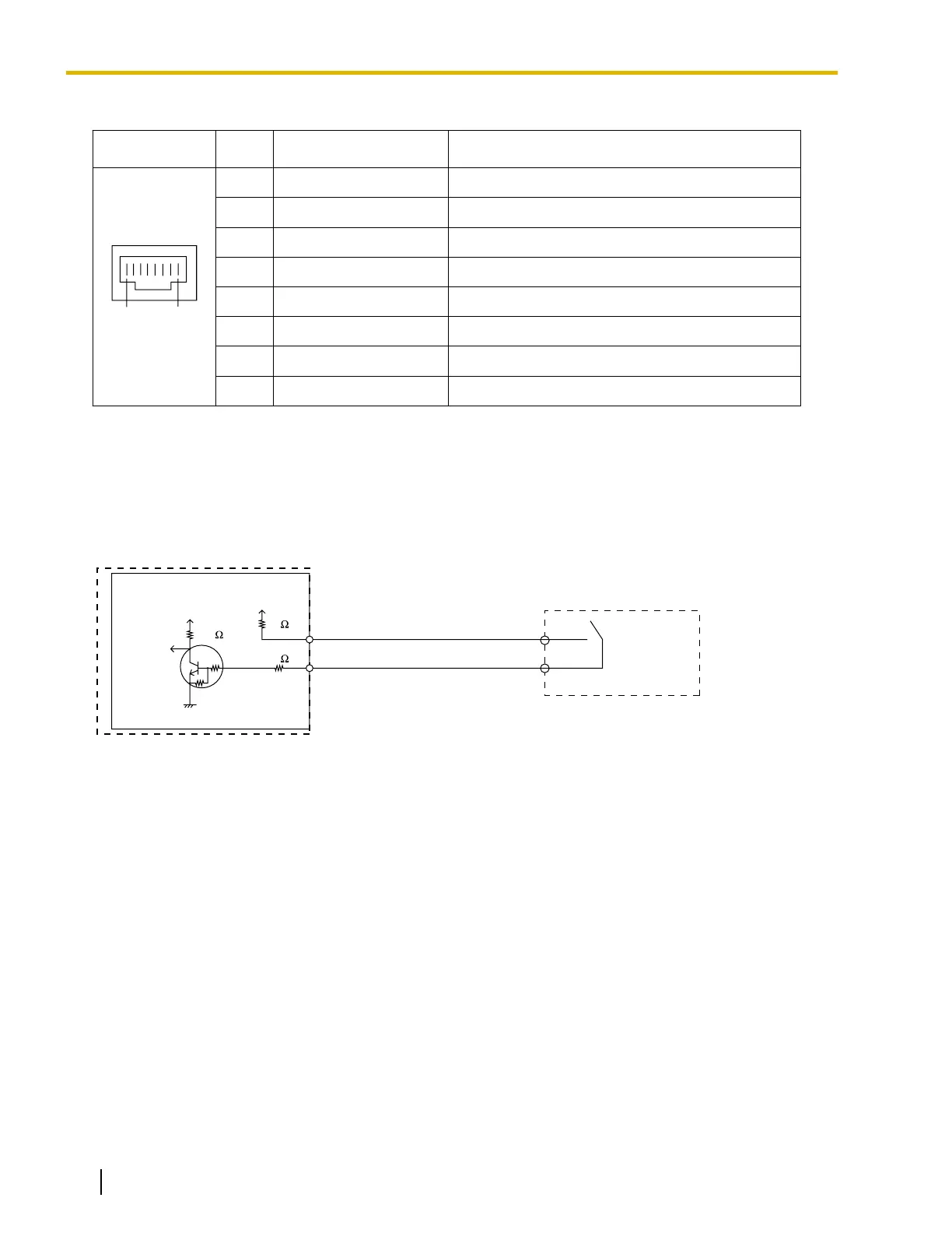
External Sensor
Power to the external sensor is provided from the
DPH2 card and must be grounded through the DPH2 card
as indicated in the diagram below. A pair of "sensor" and "common" lines are connected to the DPH2 card for
each external sensor. The PBX detects input from the sensor when the signal is under 100 W.
Connection Diagram
External Sensor
sensor
common
I/O
DOORPHONE
PBX
+3.3V
+3.3V
10K
33
33
4.7K
4.7K
Door Opener
Current Limit: 24 V DC/30 V AC, 1 A maximum
132 Installation Manual Document Version 2016-03
4.7.1 DPH2 Card (KX-NS5162)
 Loading...