6-48 Programming Your Application
590 Series DC Digital Converter
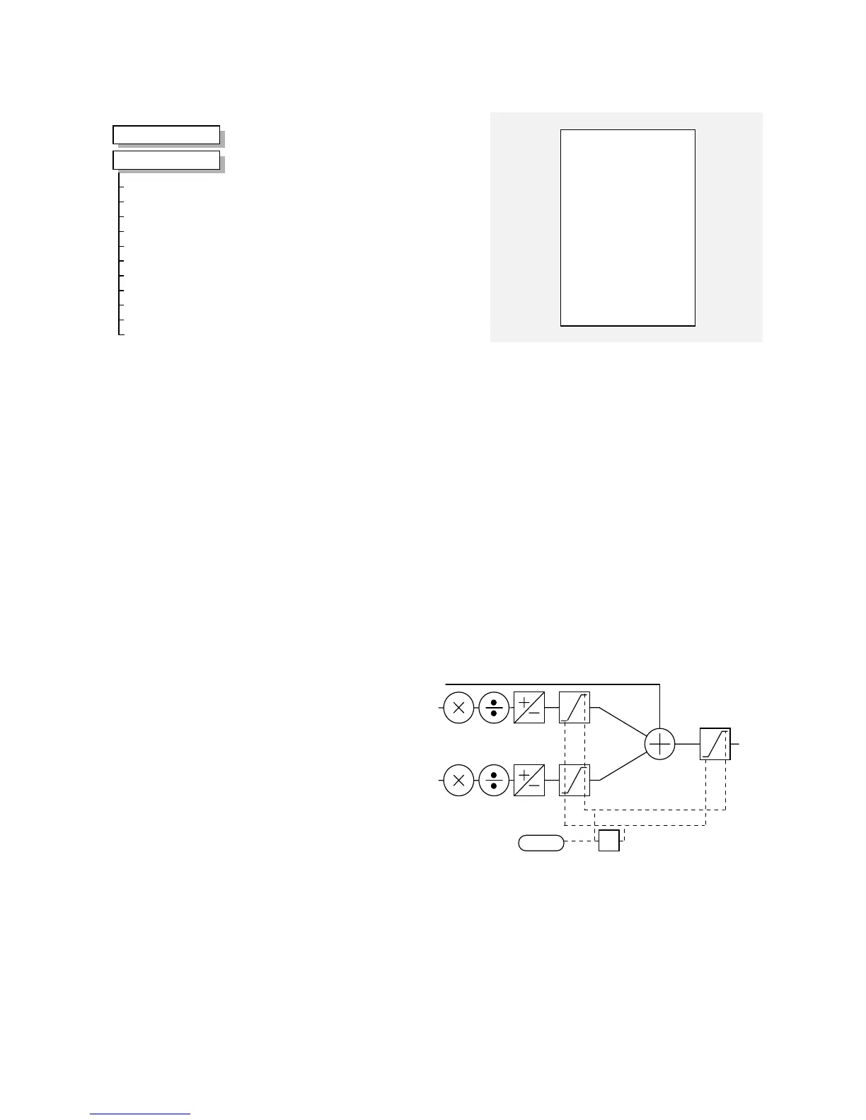
SETPOINT SUM 1
This can be configured to perform one of a
number of functions upon a fixed number
of inputs.
SETPOINT SUM 1
–
SPT. SUM 1 OUTPUT
–
0.00%
1.0000
–
[ 6] RATIO 1
–
1.0000
–
[208] RATIO 0
–
POSITIVE
–
[ 8] SIGN 1
–
POSITIVE
–
[292] SIGN 0
–
1.0000
–
[419] DIVIDER 1
–
1.0000
–
[420] DIVIDER 0
–
0.0 %
–
[131] DEADBAND
–
105.00 %
–
[375] LIMIT
–
0.00 %
–
[423] INPUT 2
–
0.00 %
–
[100] INPUT 1
–
0.00 %
–
[309] INPUT 0
–
MMI Menu Map
1
SETUP PARAMETERS
2
SETPOINT SUM 1
RATIO 1
RATIO 0
SIGN 1
SIGN 0
DIVIDER 1
DIVIDER 0
DEADBAND WIDTH
LIMIT
INPUT 2
INPUT 1
INPUT 0
Parameter Descriptions
RATIO 1
Range: -3.0000 to 3.0000
Analog input 1 scaling.
RATIO 0
Range: -3.0000 to 3.0000
Input 0 scaling.
SIGN 1
Range: POSITIVE/NEGATIVE
Analog input 1 polarity.
SIGN 0
Range: POSITIVE/NEGATIVE
Input 0 polarity.
DIVIDER 1
Range: -3.0000 to 3.0000
Analog input 1 scaling. Dividing by 0 (zero) results in a zero output.
DIVIDER 0
Range: -3.0000 to 3.0000
Input 0 scaling. Dividing by 0 (zero) results in a zero output.
DEADBAND WIDTH
Range: 0.0 to 100.0 %
Analog input 1 deadband width.
LIMIT
Range: 0.00 to 200.00 %
The Setpoint Sum
programmable limit is
symmetrical and has the
range 0.00% to 200.00%.
The limit is applied both
to the intermediate results
of the RATIO calculation
and the total output.
-1
LIMIT
INPUT 2
INPUT 1
INPUT 0
INPUT 2
Range: -200.00 to 200.00 %
Input 2 value. By default this is not connected to any analog input.
INPUT 1
Range: -200.00 to 200.00 %
Input 1 value. By default this is connected to Analog Input 1 (A2).
INPUT 0
Range: -200.00 to 200.00 %
Input 0 value. By default this is not connected to any analog input.
SPT. SUM 1 OUTPUT
Refer to the DIAGNOSTICS function block description, page 6-
18.

 Loading...
