ELECTRICAL INSTALLATION
24 ACR7000 Controller Installation Guide
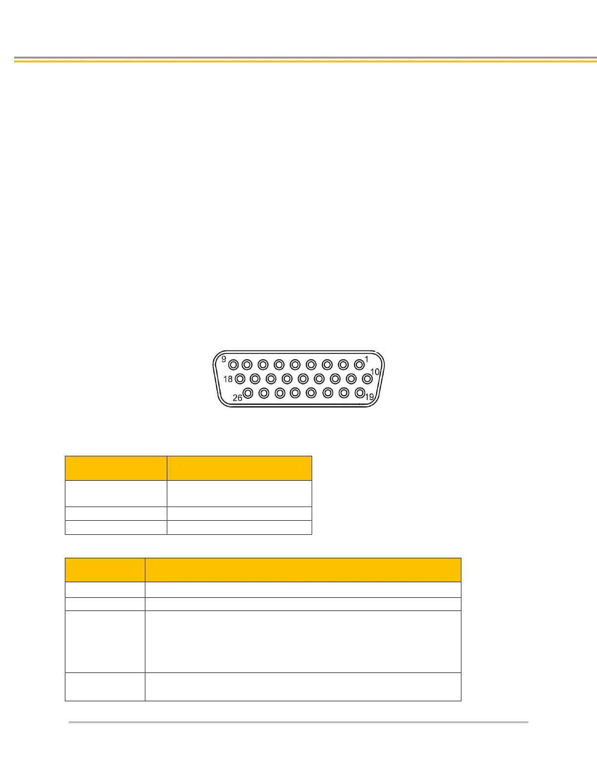
Axis Connectors
The ACR7000 controllers employ a single connector that handles both the encoder and drive signals—the Axis
connector. Depending on the configuration of the ACR7000 controller, there are four or eight axis connectors on
the front panel. They are labeled AXIS 0 through AXIS 7. The axis connector is a 26-pin, female D-sub, high-
density connector.
Functionality includes:
• +/-10V Analog command
• Step/Direction
• Drive Enable and Reset Output
• Drive Fault Input
• 5VDC source for Drive I/O
• Encoder Input
• 5VDC source for Encoder
Parker offers cables for connecting the ACR7000 controller to servo and stepper drives. Cables are
listed in the Appendix.
Figure 6. - I/O Connectors
Axis Connector Specification
Description Specification
(female socket)
Axis Connector Specification—Mating Connector
1
Description Specification
26-pin, high density D-sub, 3-row (male connector)
TE Connectivity AMP Connectors or equivalent
Cable Kit
AMP Part Number
1658679-1 includes:
1658679-1 connector
• shield
• enclosure
• two jack screws
• (does not include contacts or ferrules)
Contacts Crimp style:
TE Connectivity AMP Part Number 1658670-2
Mating connectors are not provided
 Loading...


