ELECTRICAL INSTALLATION
ACR7000 Controller Controller Installation Guide 27
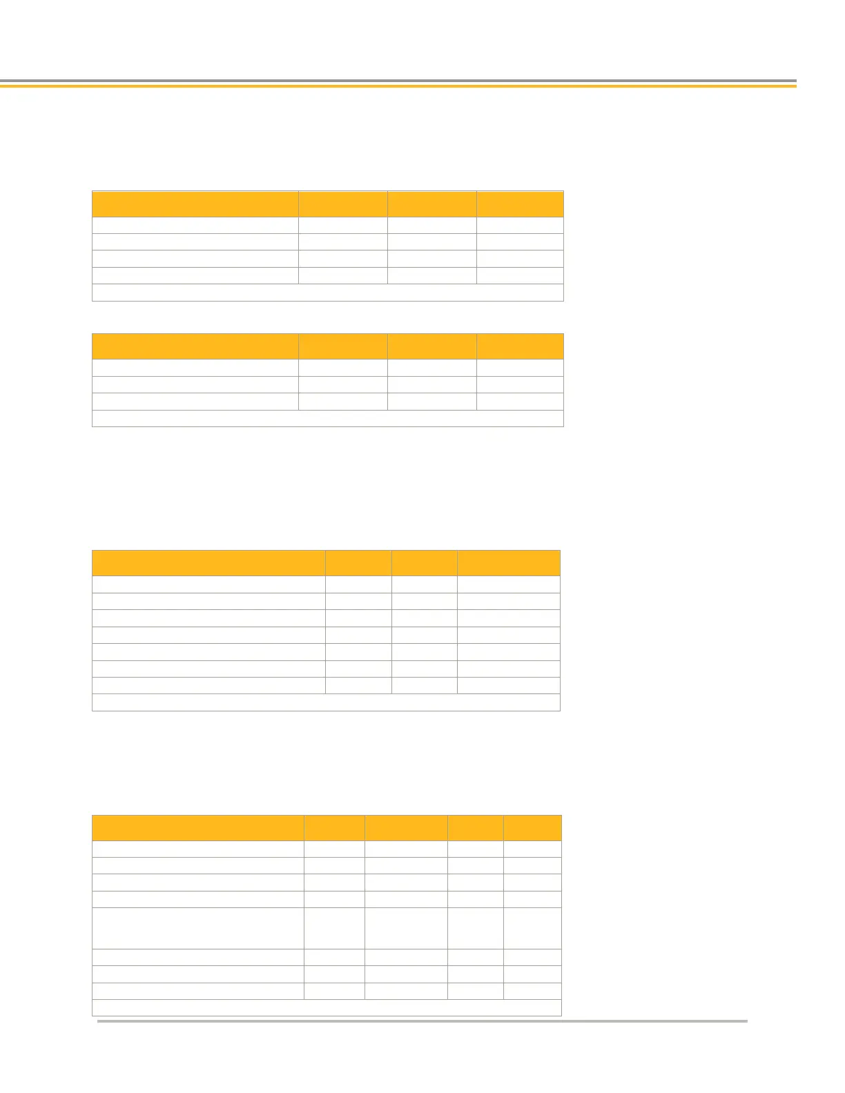
Drive Electrical/Timing Characteristics
Outputs—Drive Step and Drive Direction
Output voltage low at –30 mA
Output voltage high at +10 mA
Output voltage high at +30 mA
Note: All parameters are at the connector pin.
Outputs—Drive AOUT
Note: All parameters are at the connector pin.
Inputs—Drive Fault
• optically isolated
• Current is limited internally for input voltage control of 5 to 24-volt logic.
• Anode (+) and Cathode (−) are on separate connector pins to allow significant flexibility in wiring to
different styles of interface
Note: All parameters are at the connector pin.
Outputs—Drive Enable and Drive Reset
• not polarity sensitive and can be controlled regardless of polarity
• optically isolated. The drain and source are on separate connector pins to allow significant flexibility in
wiring to different styles of interface.
On-time voltage drop (I
L
≤ 10 mA)
On-time voltage
drop (10 mA < I
L
≤
—
—
4.0 VDC
Load current (T
A
≤ 35 °C)
Load current, I
L
(35 °C < T
A
≤ 50 °C)
Short-circuit trip current
Note: All parameters are at the connector pin.

 Loading...


