ELECTRICAL INSTALLATION
ACR7000 Controller Controller Installation Guide 25
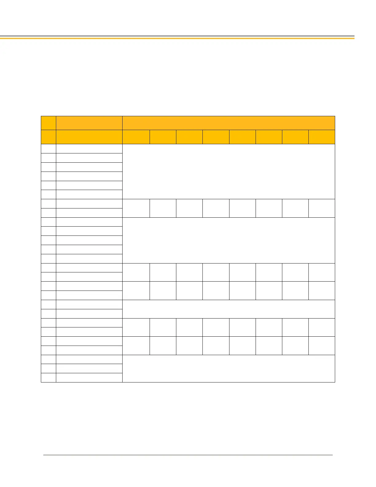
Axis Connector Pinout
Pinout configuration for the Axis connectors are listed in the following table.
Note: If the Enable Drive I/O flag is set, then the AcroBASIC direct I/O commands can only report the output
status and not set or clear the output state. The default state for all axes is Enable Drive I/O flag set.
I/O Connector Pinout
Axis Connector AcroBASIC Direct I/O Reference
Pin Signal Axis0 Axis1 Axis2 Axis3 Axis4 Axis5 Axis6 Axis7
1 5 VDC PWR
2 DC RETURN
3 Encoder CHA+
4
Encoder CHA
MRK 0 MRK 1 MRK 2 MRK 3 MRK 4 MRK 5 MRK 6 MRK 7
8
Encoder CHZ
9 5VDC PWR
10 Step+
11
Step
12 Direction+
13
Direction
P6400 P6416 P6432 P6448 P6464 P6480 P6496 P6512
BIT64 BIT65 BIT66 BIT67 BIT68 BIT69 BIT70 BIT71
18 5VDC PWR
19 Drive GND
20
Drive Enable
BIT40 BIT41 BIT42 BIT43 BIT44 BIT45 BIT46 BIT47
21 Drive Enable+
22
Drive Reset
BIT48 BIT49 BIT50 BIT51 BIT52 BIT53 BIT54 BIT55
23 Drive Reset+
 Loading...


