ELECTRICAL INSTALLATION
32 ACR7000 Controller Installation Guide
General Purpose Inputs/Outputs
The 4 Axis Configuration provides 20 general purpose (GP) digital inputs and four digital outputs through two
connections. They are labeled INPUTS (0-11) and INPUTS (24-31) / OUTPUTS (32-35). The 8 Axis Configuration
provides 40 inputs and eight outputs through four connections. The four connectors are labeled INPUTS (0-11),
INPUTS (24-31) / OUTPUTS (32-35), INPUTS (12-23), and INPUTS (72-79) / OUTPUTS (36-39).
The digital inputs and digital outputs are optically isolated from the digital logic. For inputs, current is limited
internally for input voltage control of 24-volt logic. The connectors are 25-pin female, D-subs.
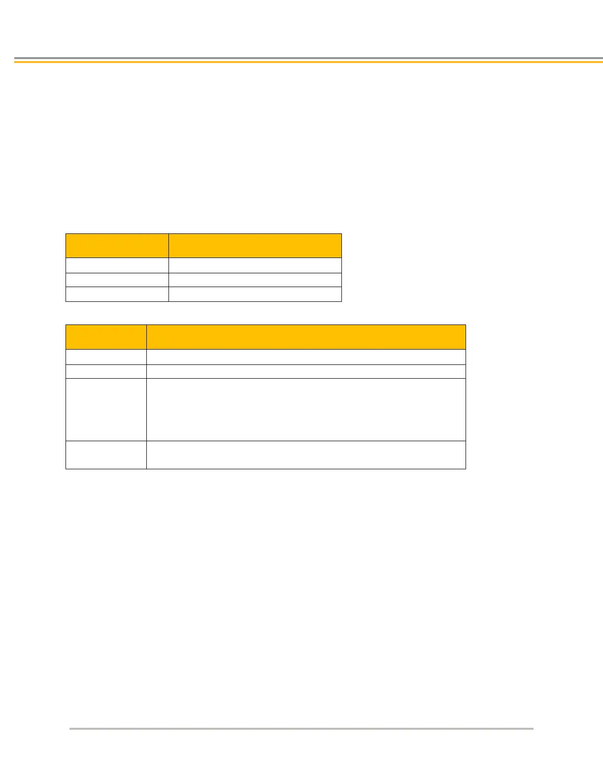
I/O Connector Specification
Description Specification
25-pin D-sub, 2-row (female socket)
I/O Connector —Mating Connector
1
Description Specification
Connector Type 25-pin, D-sub, 2-row (male connector)
TE Connectivity AMP Connectors or equivalent
Cable Kit
AMP Part Number
1658659-1includes:
1658659-1 connector
• shield
• enclosure
• two jack screws
•
(does not include contacts or ferrules)
Contacts Crimp style:
TE Connectivity AMP Part Number 166293-1
Mating connectors are not provided
 Loading...


