ELECTRICAL INSTALLATION
38 ACR7000 Controller Installation Guide
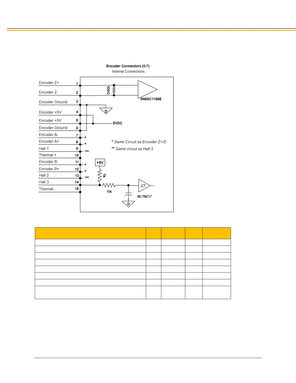
Internal Encoder 8 Connections
The following figure shows a schematic diagram of the internal connections for the Encoder 8 connector.
Encoder Inputs Specifications
Description Min Typical Max Units
Differential Threshold Voltage -200 +200 mV
Differential Termination Impedance
Thermal Switch Voltage Maximum (supplied)
(pre-quadrature)
 Loading...


