EasyManuals Logo

Parker ACR7000 User Manual

Parker ACR7000
61 pages
To Next Page IconTo Next Page
To Previous Page IconTo Previous Page
Page #34 background imageLoading...
Page #34 background image
ELECTRICAL INSTALLATION
34 ACR7000 Controller Installation Guide
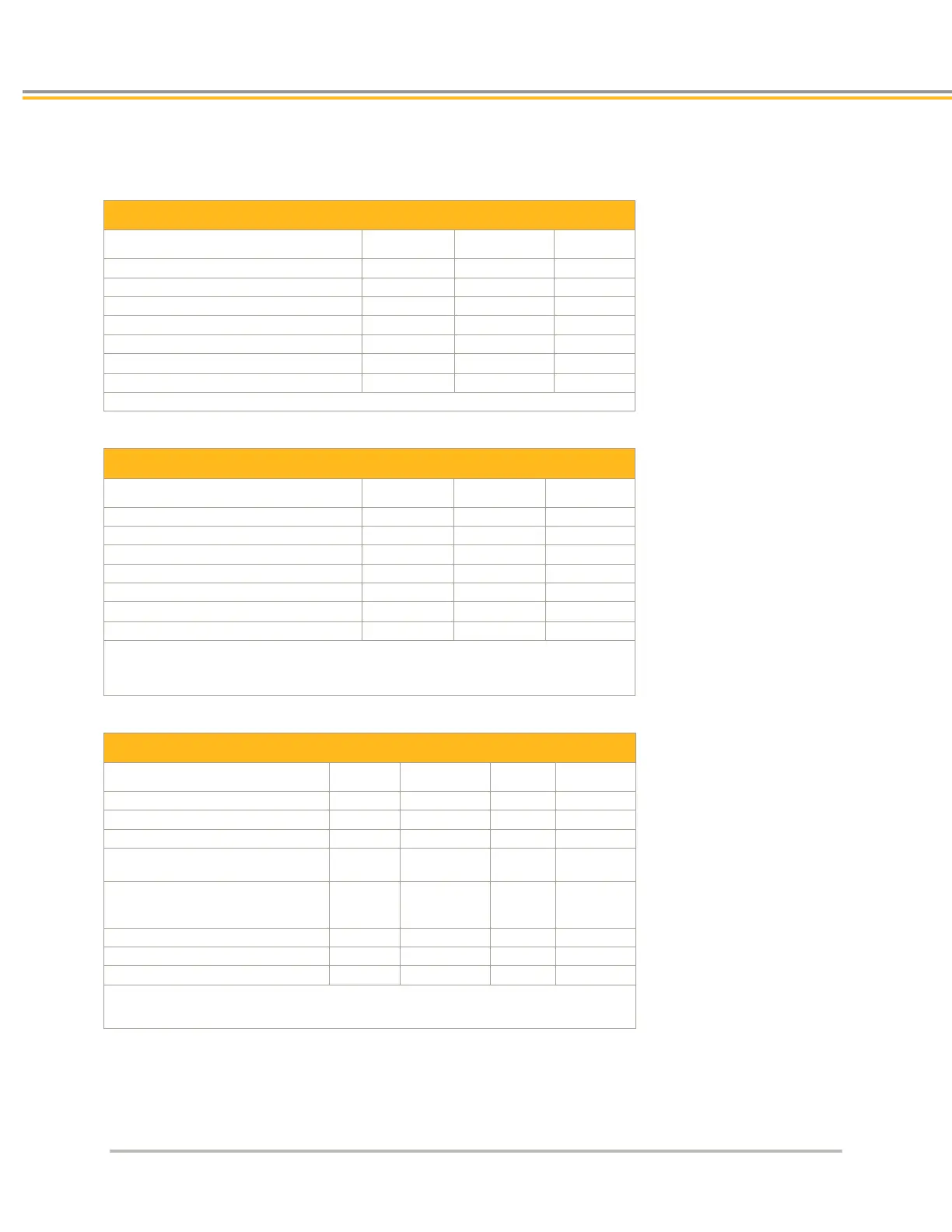
Input/Output Electrical/Timing Characteristics
GP Inputs 011, 1223
Description
Min
Max
Units
Turn-on time
--
1
ms
Turn-off time
--
1
ms
Guaranteed on voltage
21
--
VDC
Guaranteed off voltage
--
3
VDC
Maximum forward voltage
--
30
VDC
Maximum reverse voltage
30
--
VDC
Forward current
6.3
15
mA
Note: All parameters are at the connector pin.
Trigger Inputs 2431, 7279
Description
Min
Max
Units
Turn-on time
--
400
ns
Turn-off time
--
400
ns
Guaranteed on voltage
21
--
VDC
Guaranteed off voltage
--
3
VDC
Maximum forward voltage
--
30
VDC
Maximum reverse voltage
30
--
VDC
Forward current
6.3
15
mA
Note: All parameters are at the connector pin.
Propagation delay due to filtering and isolation is ~400 ns, or encoder capture
resolution of +/ 5 counts at 10 MHz.
GP Outputs 3239
Description
Min
Typical
Max
Units
Turn-on time
--
--
2
ms
Turn-off time
--
--
1
ms
Working voltage
-30
1
--
30
VDC
On-Time voltage
drop (I
L
≤ 10 mA)
-- -- 0.4 VDC
On-time voltage
drop (10 mA < I
L
100 mA)
-- -- 4.0 VDC
Load current (T
A
≤ 35 °C)
--
--
100
mA
Load current, I
L
(35 °C < T
A
≤ 50 °C)
--
--
80
mA
Short-Circuit trip current
--
200
--
mA
1. The output is not polarity sensitivity and can be controlled regardless of polarity.
Note: All parameters are at the connector pin.

Table of Contents

Other manuals for Parker ACR7000

Questions and Answers:

Question and Answer IconNeed help?

Do you have a question about the Parker ACR7000 and is the answer not in the manual?

Parker ACR7000 Specifications

General IconGeneral
BrandParker
ModelACR7000
CategoryController
LanguageEnglish

Related product manuals