COMMUNICATIONS
46 ACR7000 Controller Installation Guide
Ethernet Connector Pinout
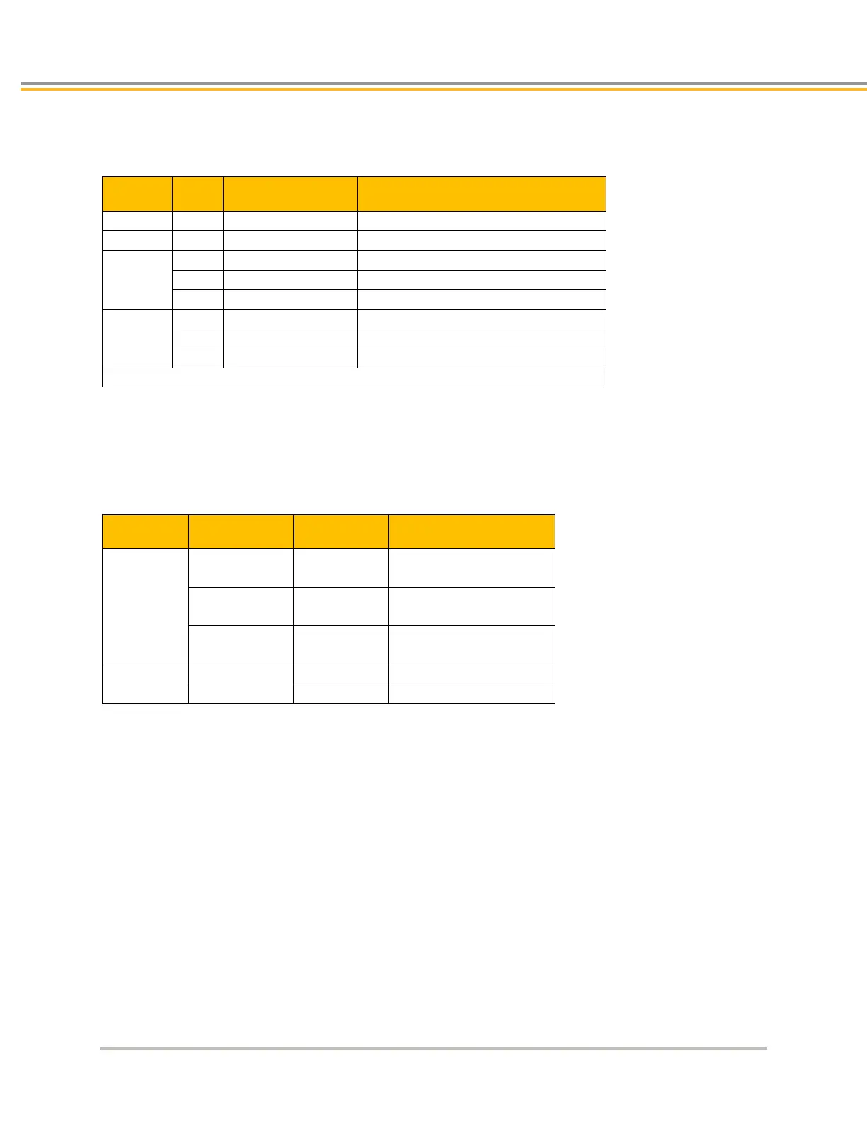
The following table contains the Ethernet connector pinout.
RJ-45 Connector Pinout
Signal Pin Wire Color Description
Differential Receive positive side
Differential Receive negative side
TX+
3 White with green Differential Transmit positive side
TX-
Differential Transmit negative side
Note: Pin assignment follows EIA/TIA T568B guidelines.
RJ-45 LED Ethernet Status Indicators
LEDs located on the RJ-45 socket connector indicate Ethernet status. The next table describes the LED states and
their meanings.
RJ-45 Ethernet Status LED Indications
Signal Steady Flash Description
Ethernet
Link/Activity
Off —
detected
Yellow —
Ethernet link established,
no activity
— Yellow
Ethernet link established
and active
Speed

 Loading...


