ELECTRICAL INSTALLATION
ACR7000 Controller Controller Installation Guide 23
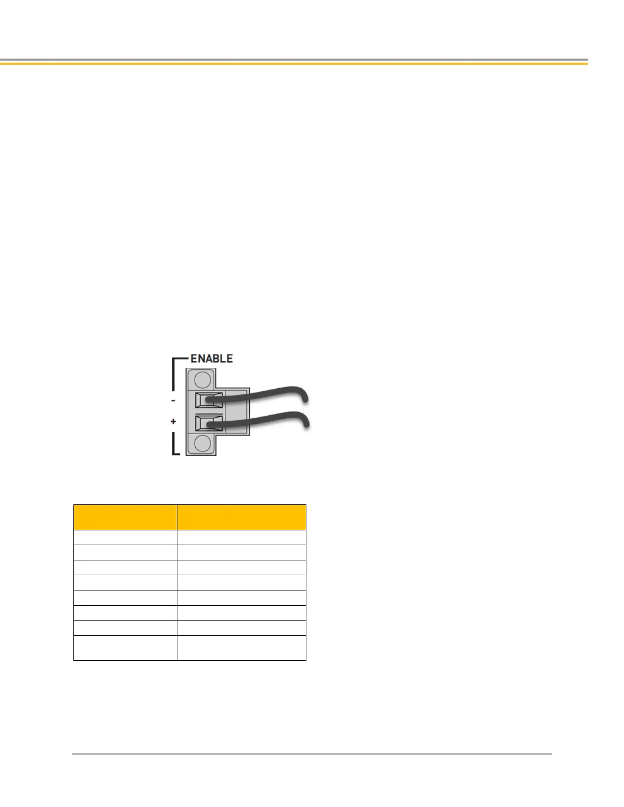
ENABLE – Enable Input Connector
The Enable Input must be connected to 24VDC in order to enable external drives and provide command signals. If
the input goes inactive, that inactive state is latched and the ACR7000 reacts by doing the following:
• Disabling the drives
• Blocking motion command signals
The status of the motion enable input is shown in BIT5646, where active is a cleared or 0 state, and inactive is a
set or 1 state.
When the enable input goes inactive, BIT5645 is set and latched until voltage is present again on the enable input
and either:
• The DRIVE ON command is issued for one of the Axes or,
• Clear Motion Enable Input Latch bit is asserted, SET BIT 5647
NOTE: The Motion Enable Input can be used as a part of a circuit to prevent motion and remove power from the
motors. Note that if the input is deactivated while in motion, motors will stop immediately without a deceleration
ramp.
Enable Connector
Description Specification
Connector Type Removable screw terminal
Terminals 2
Pitch 0.200 in (5.08 mm)
Wire range 12-24 AWG (0.34-2.5 mm2)
Wire strip length 0.3 in (7-8 mm)
Torque 5 in–lbs. nom. (0.5 N-m)
Manufacturer OnShore or equivalent
OnShore Part Number
OSTTJ025152 (green)

 Loading...


