ELECTRICAL INSTALLATION
ACR7000 Controller Controller Installation Guide 37
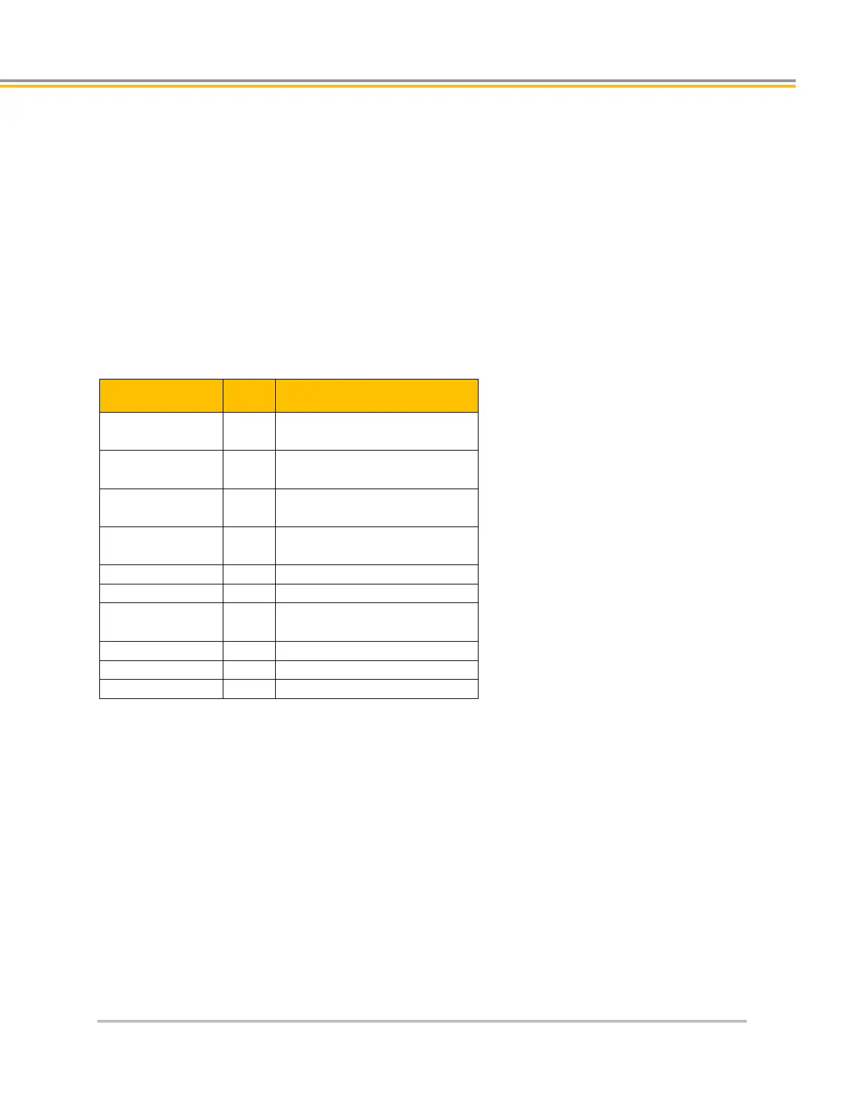
Encoder Connector (ENC8) Pinout
Pinout configuration for the Encoder connectors 8 is listed in the following table. A box surrounding pins indicates
a requirement for twisted pair wiring.
Two digital inputs are present on ENC8 connector
• High speed for encoder position capture functions (INTCAP)
• Schmitt Trigger with Zener Diode and RC filter, non-isolated.
• Short circuited protected
• 24VDC pull-up, 4.75k resistor
• Inputs are active when switched to DGND
• Compatible with NPN sensors
Encoder 8 Connector Pinout
Signal Pin Incremental Encoder
ENC Z+
ENC Z–
1
2
Encoder Z Channel in
Encoder Z Channel in
+5 VDC
4
+5 VDC Encoder power
DGND
6
Encoder power return
ENC A–
ENC A+
7
8
Encoder A Channel in
Encoder A Channel in
ENC B+
12
Encoder B Channel in
Hall 2 13 Hall 2 input
 Loading...


