43
24 V DC - Design
NOTE!
Use of the control head in explosive atmosphere
• Only use cables and cable glands which are approved for the respective application area and fit the cable
glands according to the respective operating instructions!
• Close all unnecessary openings with lock screws/plugs approved for explosions area!
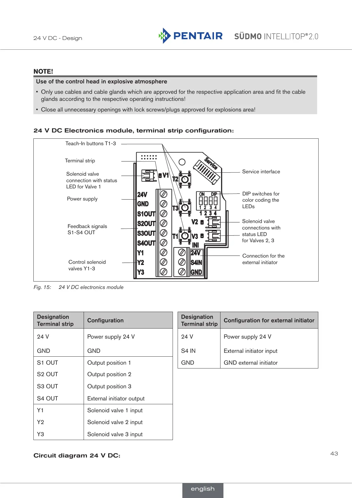
24 V DC Electronics module, terminal strip configuration:
Solenoid valve
connection with status
LED for Valve 1
Power supply
Service interface
DIP switches for
color coding the
LEDs
Connection for the
external initiator
Feedback signals
S1-S4 OUT
Control solenoid
valves Y1-3
Teach-In buttons T1-3
Solenoid valve
connections with
status LED
for Valves 2, 3
Terminal strip
Fig. 15: 24 V DC electronics module
Designation
Terminal strip
Configuration
Designation
Terminal strip
Configuration for external initiator
24 V Power supply 24 V 24 V Power supply 24 V
GND GND S4 IN External initiator input
S1 OUT Output position 1 GND GND external initiator
S2 OUT Output position 2
S3 OUT Output position 3
S4 OUT External initiator output
Y1 Solenoid valve 1 input
Y2 Solenoid valve 2 input
Y3 Solenoid valve 3 input
Circuit diagram 24 V DC:
english
 Loading...