73
120 V AC Design
Designation
Terminal strip
Configuration
Designation
Terminal strip
Configuration for external
initiator
PE Protection earth protective conductor L Power supply - conductor
L Conductor Power S4 IN External initiator input
N
Neutral
conductor
supply 120 V AC N Power supply - neutral conductor
S1 OUT Output position 1
S2 OUT Output position 2
S3 OUT Output position 3
S4 OUT External initiator output
Y1 Solenoid valve 1 input
Y2 Solenoid valve 2 input
Y3 Solenoid valve 3 input
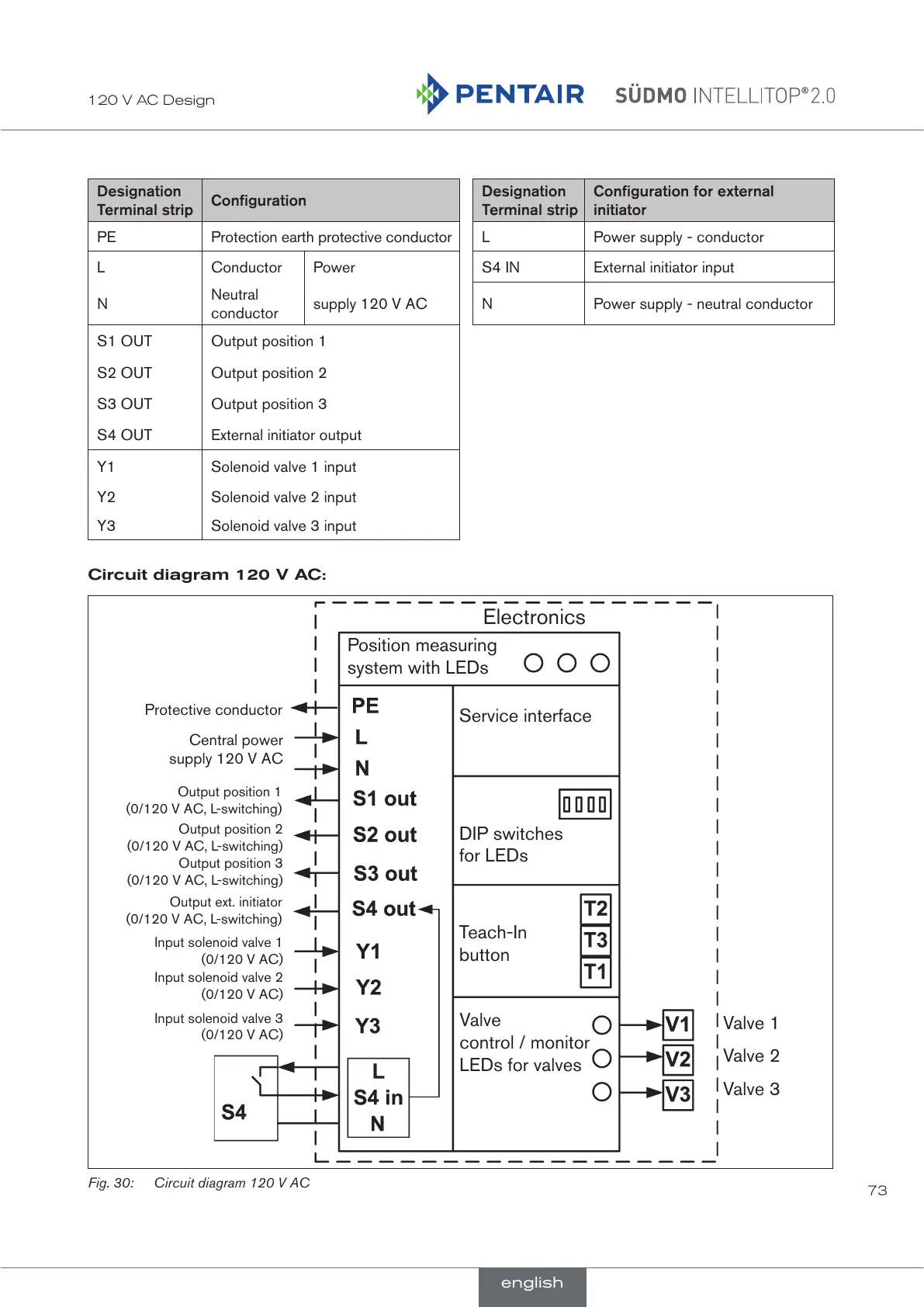
Circuit diagram 120 V AC:
Electronics
Position measuring
system with LEDs
Service interface
DIP switches
for LEDs
Teach-In
button
Valve
control / monitor
LEDs for valves
Valve 1
Valve 2
Valve 3
Central power
supply 120 V AC
Protective conductor
Output position 1
(0/120 V AC, L-switching)
Output ext. initiator
(0/120 V AC, L-switching)
Input solenoid valve 1
(0/120 V AC)
Input solenoid valve 2
(0/120 V AC)
Input solenoid valve 3
(0/120 V AC)
Output position 2
(0/120 V AC, L-switching)
Output position 3
(0/120 V AC, L-switching)
Fig. 30: Circuit diagram 120 V AC
english
 Loading...