25
A4 Dismantling
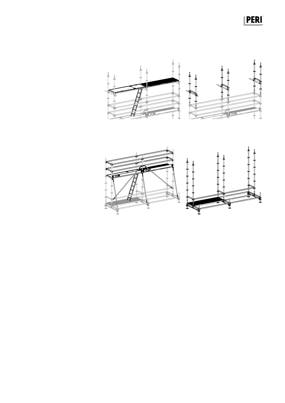
3. From a position on the next level
below:
– Ladder, access deck and top Decks
UDG (Fig. A4.03a)
– Pressure-resistant ties
– Ledger UH 75
– Locking Pins Ø 48/57
– Standards UVR (Fig. A4.03b)
– Continuously dismantle reinforce-
ment scaffold in this sequence
4. Dismantling the base level:
Dismantling to take place in this order:
– Ledger Braces UBL and Toeboards
– Ledger UH 75 and Ledger UH
– Ladder, access deck and Decks UDG
– Node Brace UBK (Fig. A4.04a)
– Ledger UH 75 and Ledger UH
– Locking Pins Ø 48/57
– Standards UVR
– Ledger-to-Ledger Coupler UHA Half
with Spigot
– Ledger UHV 150 Plus
– Spindle Locking UJS
– Base Standard UVB (Fig. A4.04b)
Fig. A4.03a Fig. A4.03b
Fig. A4.04a Fig. A4.04b
3.
4.
PERI UP Flex Reinforcement Scaffold 75 and 100
Instructions for Assembly and Use – Standard Configuration