44
D1 Moving by crane
Scaffold width 75 cm (100 cm)
Standing
height
[cm]
Base width 150 cm
Assembly on UHV 150
Base width 250 cm
Assembly on UHV 250 / UVA 250
Standing
height
[cm]
1 bay
300 cm
2 bays
600 cm
3 bays
900 cm
1 bay
300 cm
2 bays
600 cm
3 bays
900 cm
max. dead load [kg] max. dead load [kg]
224 – 260 310
(340)
500
(550)
680
(760)
400
(430)
640
(700)
880
(960)
224 – 260 /
248 – 280
424 – 460 450
(510)
750
(850)
1040
(118 0)
540
(600)
890
(990)
1230
(1380)
424 – 460 /
448 – 480
624 – 660 590
(680)
990
(1140)
1390
(1600)
680
(770)
1130
(1290)
1580
(1800)
624 – 660 /
648 – 680
820
(930)
1380
(1580)
1940
(2230)
824 – 860 /
848 – 880
960
(1100)
1630
(1880)
2290
(2650)
1024 – 1060 /
1048 – 1080
Table D1.01
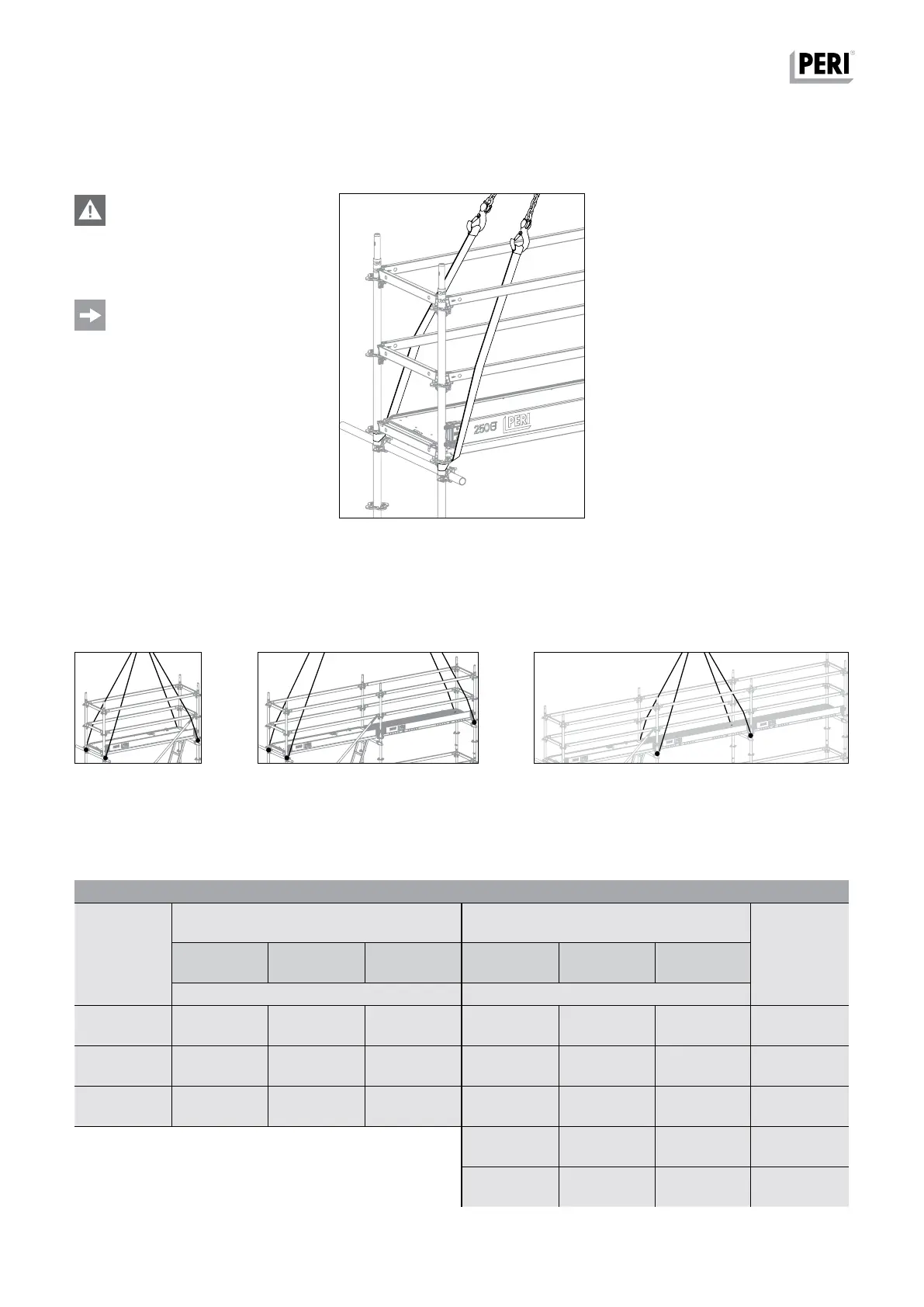
Danger
Risk of injury!
Do not stand under the suspended
load.
Requirements:
– Ensure that all Standards are tightly
connected!
– Remove loose parts!
Load-bearing points
For moving by crane, webbing belts for
example can directly be wrapped
around the Standards under the ro-
settes (Fig. D1.01). The complete rein-
forcement scaffold unit is moved using
four-sling lifting gear (Fig. D1.01a +
D1.01b + D1.01c).
Fig. D1.01cFig. D1.01b
Fig. D1.01
Fig. D1.01a
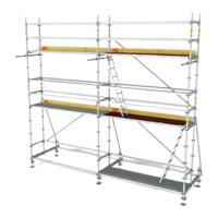
PERI UP Flex Reinforcement Scaffold 75 and 100
Instructions for Assembly and Use – Standard Configuration
Dead loads