35
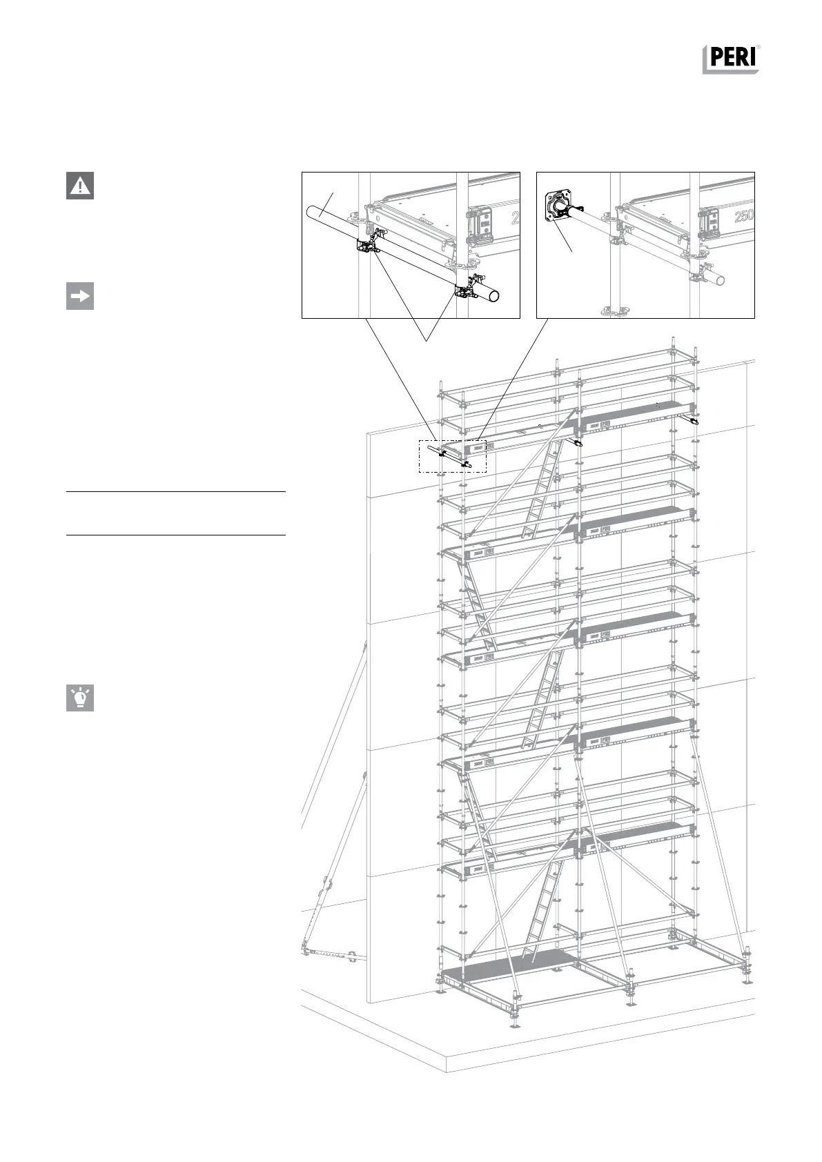
B3 Pressure-resistant ties
Fig. B3.01
19
13
1
Fig. B3.01a
Fig. B3.01b
Danger
Risk of injury!
The Adjustable Base Plate UJS (1)
must be secured to prevent falling
out. (Fig. A3.01b)
Compression forces to the wall or
formwork are to be verified on site by
the contractor!
With standing heights of 424 cm and
more, pressure-resistant ties are to be
mounted on all Standards – directly un-
der the highest deck level – and posi-
tioned up against the wall or formwork.
Pos. Component Qty.
13
Steel Scaffold Tube Ø 48.3 x 3.2
3x
19 Standard Coupling NK 48/48 6x
Assembly
Directly under highest deck level.
1. Securely fix the scaffold tube (13) to
the Standard UVR using Standard
Couplers (19).
2. Adjust distance of scaffold tube from
the wall.
PERI recommends inserting an Adjust-
able Base Plate UJS (1) into the scaf-
folding tube if the distance to the wall
has to be adjusted more often. Secure
Adjustable Base Plates against falling
out. (Fig. B3.01b)
PERI UP Flex Reinforcement Scaffold 75 and 100
Instructions for Assembly and Use – Standard Configuration