Sequence and times must be strictly observed or
it will be necessary to repeat the procedure from
the start.
Once the control unit has been programmed, the
control unit is inseparably matched with the MAS-
TER key transponder.
This matching allows programming further service
keys in case of loss, replacement, etc. Each new
time new data is programmed the previously stor-
ed one is deleted.
If a service key setting is lost, it is essential to
carefully check the efficiency of the high voltage
system:
Shielded cap resistance ~ 5000 Ω.
In any case it is advisable to use resistive spark
plugs.
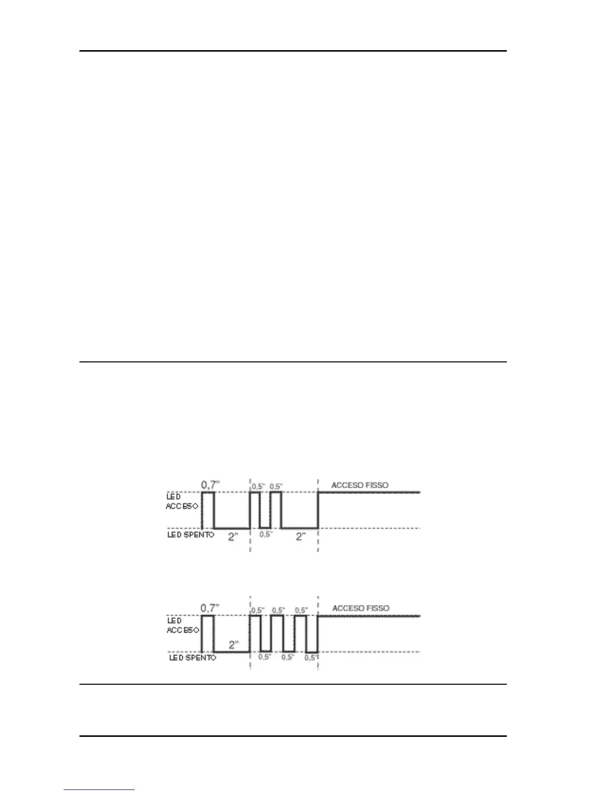
Diagnostic codes
The flash indicating the switching to "ON" can be followed by a phase of programmed failure warnings.
That is, the led is off for 2 seconds, and then diagnosis codes are transmitted with 0.5-second flashes.
After the failure code indication, a steadily on LED signals that ignition is disabled; see the table:
2-FLASH CODE - Example with programmed control unit, no transponder and/or malfunctioning aerial.
Ignition disabled-Vehicle immobilised
3-FLASH CODE - Example with programmed control unit, aerial working properly and unknown trans-
ponder code. Ignition disabled-Vehicle immobilised
Diagnostic code - 2 flashes
Diagnosis code: 2-flashes
Electrical system MSS X9 Evolution 250
ELE SYS - 62