EasyManuals Logo

Pioneer MEP-7000 Service Manual

Pioneer MEP-7000
286 pages
To Next Page IconTo Next Page
To Previous Page IconTo Previous Page
Page #234 background imageLoading...
Page #234 background image
234
MEP-7000
1
2 3 4
A
B
C
D
E
F
1
2 3 4
149
150
151
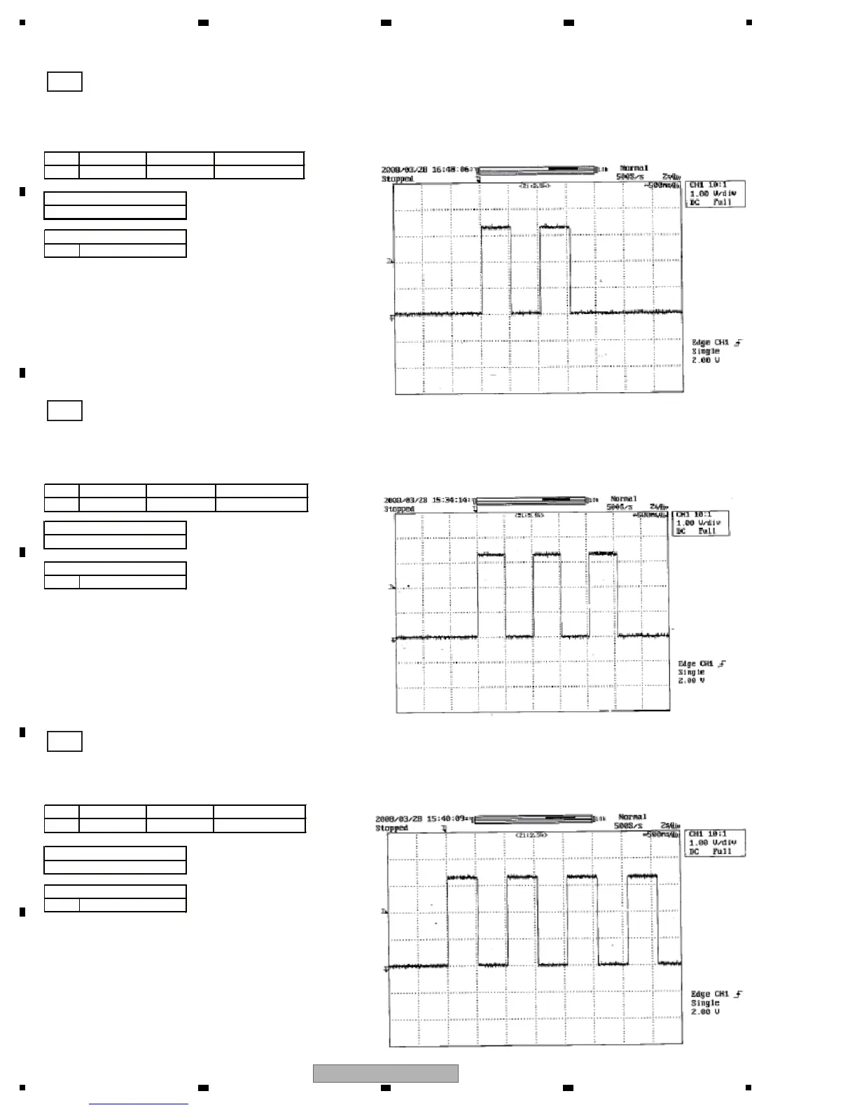
If configuration of the USB controller has not been completed
Communication failure of the North CPU, which cannot be judged with the status LEDs,
can be judged with the pulse waveform output from Pin 2 of the CPLD (IC1700).
CH1
If communication with the video encoder failed
CH1
If communication with the center panel microcomputer failed
CH1
1.0V/div
20µs/div
1.0V/div
20µs/div
20µs/div
1.0V/div
No.(SCH/PCB)
CH1 - 151 IC1700(2P)
No.(SCH/PCB)
CH1 - 151 IC1700(2P)
No.(SCH/PCB)
CH1 - 151 IC1700(2P)
[15] NMAIN: DEBUG SIGNAL WAVEFORMS
Voltage
Time
Signal Name
Measurement Point
Voltage
Time
Signal Name
Measurement Point
Voltage
Time
Signal Name
Measurement Point
CPLD waveform for auto device diagnosis

Table of Contents

Other manuals for Pioneer MEP-7000

Questions and Answers:

Question and Answer IconNeed help?

Do you have a question about the Pioneer MEP-7000 and is the answer not in the manual?

Pioneer MEP-7000 Specifications

General IconGeneral
Frequency range4 - 20000 Hz
Channels quantity- channels
Digital sound processing- bit
Total Harmonic Distortion (THD)0.006 %
Dimensions (WxDxH)483 x 325 x 91 mm
Power consumption (typical)33 W
Weight and Dimensions IconWeight and Dimensions
Weight6100 g

Related product manuals