User’s Manual of GS-4210-16T2S_24T2S_16P2S_24P2S_48T4S
Step 5: Supplying power to the Managed Switch.
Connect one end of the power cable to the Managed Switch and the power plug of the power cable to a standard wall
outlet. When the Managed Switch receives power, the Power LED should remain solid Green.
2.2.2 Rack Mounting
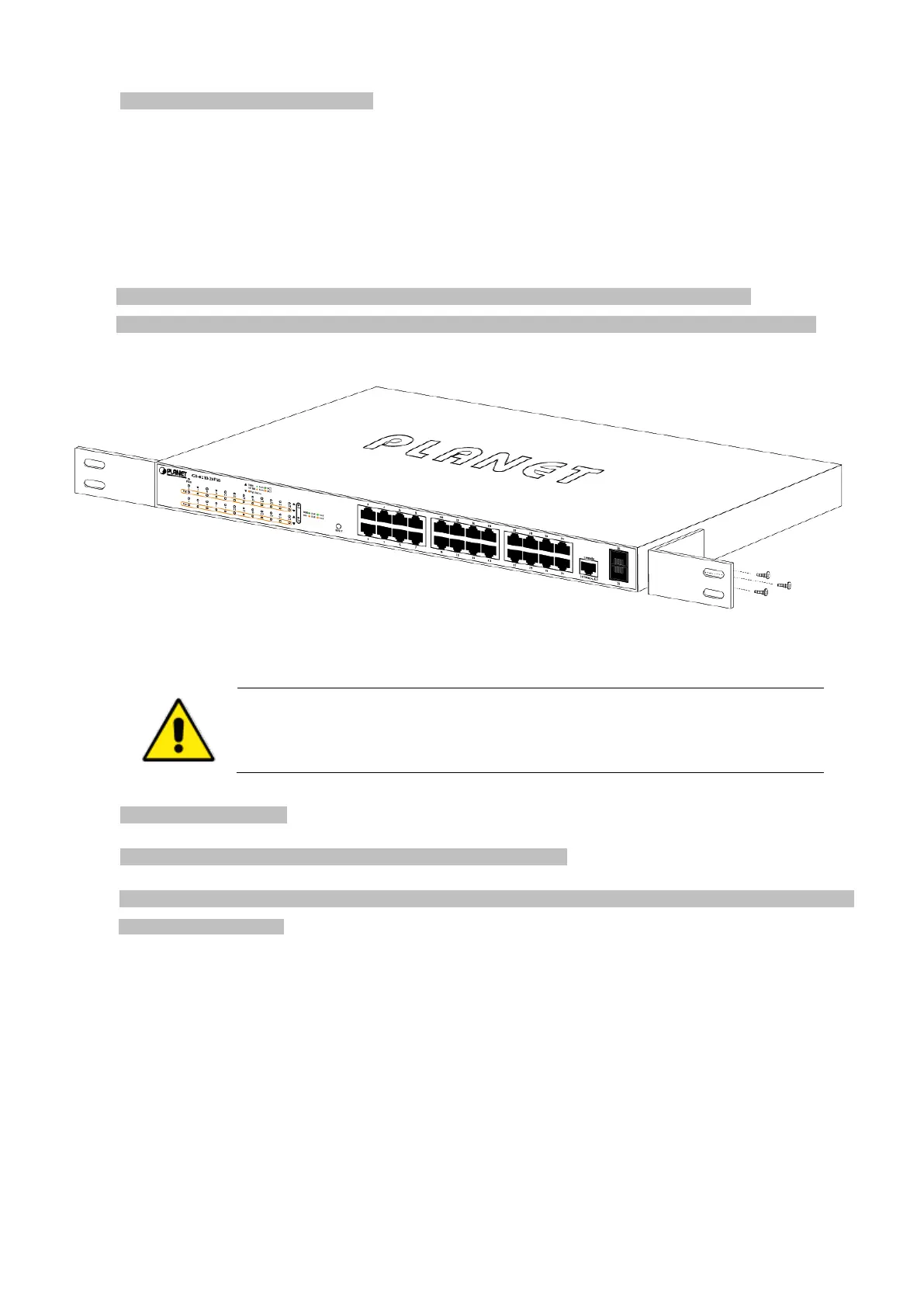
To install the Managed Switch in a 19-inch standard rack, please follow the instructions described below.
Step1: Place the Managed Switch on a hard flat surface, with the front panel positioned towards the front side.
Step2: Attach the rack-mount bracket to each side of the Managed Switch with supplied screws attached to the package.
Figure 2-1-15 shows how to attach brackets to one side of the Managed Switch.
Figure 2-1-15: Attach Brackets to the Managed Switch
You must use the screws supplied with the mounting bra
ckets. Damage caused to the parts by
using incorrect screws would invalidate the warranty.
Step 3: Secure the brackets tightly.
Step 4: Follow the same steps to attach the second bracket to the opposite side.
Step 5: After the brackets are attached to the Managed Switch, use suitable screws to securely attach the brackets to the rack,
as shown in Figure 2-1-16.
 Loading...