User’s Manual of MGSW-28240F
voltage from -36V to -72V DC. Connect the power cable to the Managed Switch at the input terminal block. The size of the
two screws in the terminal block is M3.5.
■ Digital Input
The digitail input of the Managed Switch can be activated by the external sensor that senses physical changes. These
changes can include intrusion detection or certain physical change in the monitored area. For example, the external sensor
can be a door switch or an infrared motion detector.
■ Digital Output
The digital output main function is to allow the Managed Switch to trigger external devices, either automatically or by
remote control from a human operator or a software application.
2.1.2 LED Indications
System
LED Color Function
Ring Green
Lights Indicates that Ring state is in idle mode.
Blink Indicates that the Ring state is in protected mode.
R.O. Green
Lights Indicates that the switch is set to ring owner.
Off Indicates that the switch doesn’t set to ring owner.
DC1 Green Lights Indicates that the Switch is powered on by DC1 input.
DC2 Green
Lights
Indicates that the Switch is powered on by DC2 input.
FAN1 Green
Lights
Indicates that the FAN1 has stopped.
FAN2 Green
Lights
Indicates that the FAN2 has stopped.
Fault Green
Lights
Indicates that Switch AC/DC or port has failed.
PWR Green
Lights Indicates that the Switch is powered on.
Blink Indicates the System is running under booting procedure.
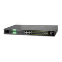
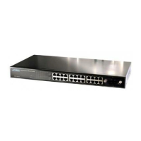
10/100/1000Base-T interfaces for port1 to port24 SFP slot
LED Color Function
LNK/ACT Green
Lights
Indicates the link through that SFP port is successfully established
1000Mbps.
Blink Indicates that the switch is actively sending or receiving data over that port.
Off Indicates that the SFP port is link down.

 Loading...