User’s Manual of MGSW-28240F
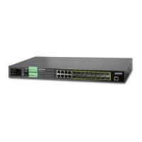
Figure 2-3: MGSW-28240F Upper Panel
2. Tighten the wire-clamp screws for preventing the wires from loosening.
Figure 2-4 6-Pin Terminal Block Power Wiring Input
1. The wire gauge for the terminal block should be in the range of 12 ~ 24 AWG.
2. When performing any of the procedures like inserting the wires or tighten the wire-clamp screws,
make sure the power is OFF to prevent from getting an electric shock.
2.1.5 Wiring the Faulty Alarm Contact
The fault alarm contacts are in the middle (3 & 4) of the terminal block connector as the picture shows below. Inserting the wires,
the Managed Switch will detect the fault status of the power failure, or port link failure (available for managed model) when
Fault Alarm function has been enabled. The following illustration shows an application example for wiring the fault alarm
contacts

 Loading...