Names of the Parts
CAUTION
• Atleasttwopersonsshouldholdthemainunit.Ifnot,themainunitcoulddroportip,resultinginaccidentalinjury.
• Lockthestand’scastersbypressingthebottomofthecasterlockbutton.Ifnot,thestandcouldmovewhilethemain
unitisbeingmountedorremoved,resultinginaccidentalinjury.
• Afterunpluggingthepowercordfromthewallpoweroutlet,disconnectalltheconnectioncordsfromtheset’sinput/
outputterminals.Ifthesetisremovedwithoutdisconnectingthecords,itcouldtip,resultinginaccidentalinjury.
• Ifaprinterismountedontheset,removetheprinterbeforestarting.Ifnot,thestandcouldtipwhilethemainunitis
beingmountedorremoved,resultinginaccidentalinjuryduetotheprinterdroppingortippingover.
(1) Unplug the power cord from the wall power outlet, then disconnect all the connection cords
from the main unit.
(2) Remove the locking knobs (one on each side).
(3) Change the position of the main unit support pieces.
Lift the main unit about 1 cm to unhook it.
Insert the stand’s hooks securely into in the mounting holes in the main unit’s support pieces (one
on each side).
(4) Fasten the two locking knobs (left and right) to the mount support pieces.
(5) Connect all the connection cables.
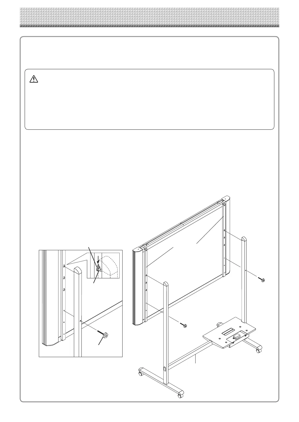
Changing the Height of the Unit
This is the height adjustment when setting up the captureboard on the optional stand. The stand height can
be adjusted to 3 levels by 100 mm.
* Thisillustrationdoesnotshowtheconnectioncords.
lock-screws
lock-screw
Hook
Mountinghole
Rearframes
Stand
https://www.supplychimp.com/