3.194
9928485 R01 - 2017-2018 RANGER 500 / 570 Service Manual
© Copyright Polaris Industries Inc.
CRANKSHAFT REMOVAL
1. Remove the engine from the engine stand and place
the assembly on a sturdy work bench.
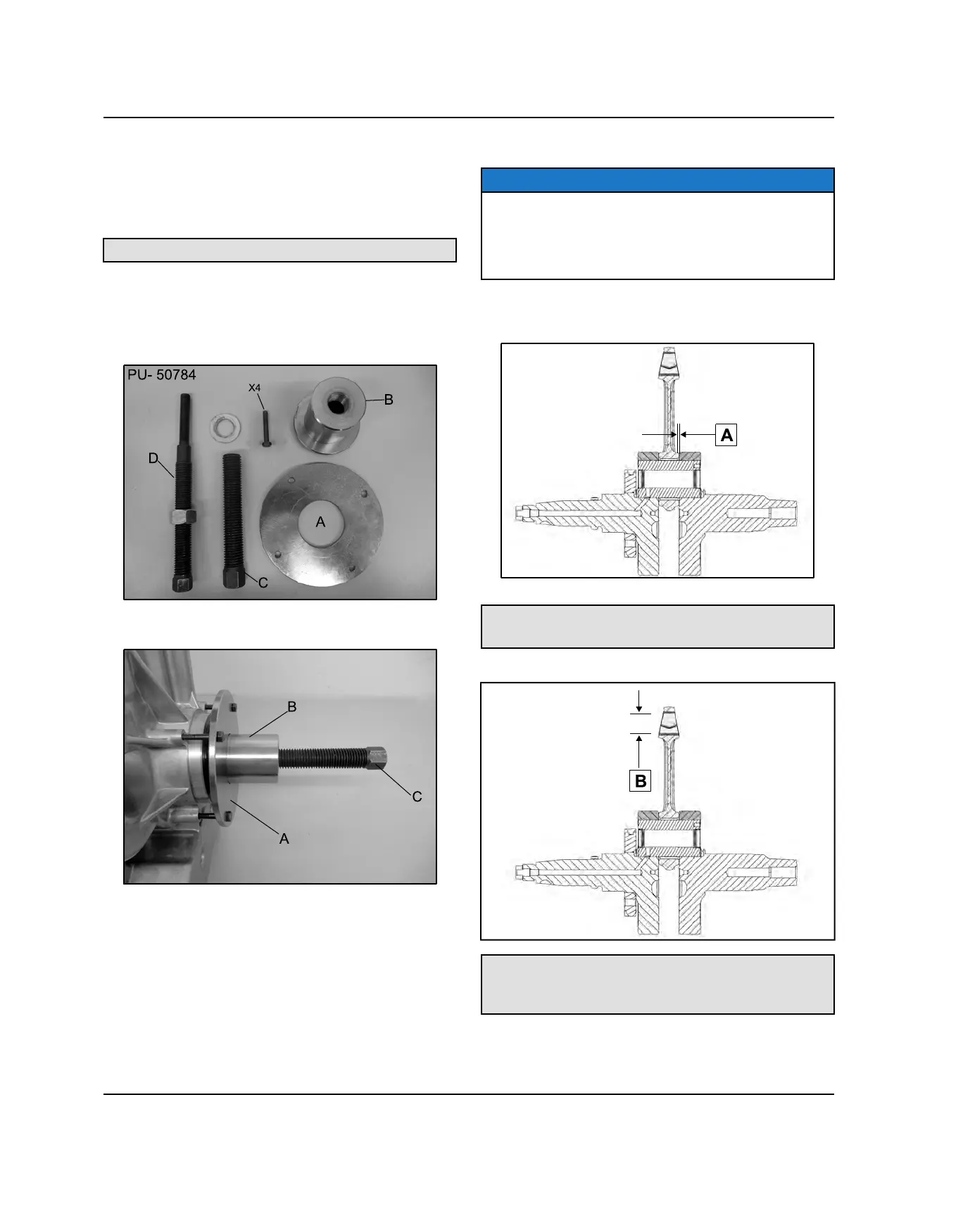
2. Install the crankshaft removal / installation tool on to
the PTO side crank case.
Crankshaft Removal / Installation Tool: PU-50784
• Install plate “A” over adapter “B”.
• Evenly attach the assembly onto the PTO side
crankcase using the (4) bolts as shown below.
• Thread the crankshaft removal screw “C” into adapter
“B”.
3. With the help of an assistant holding the crankshaft,
slowly tighten the screw “C” until the crankcase is
completely separated from the crankshaft.
4. Remove all special tools from the crankcase.
CRANKSHAFT INSPECTION
NOTE
The connecting rod uses plain bearings. The
connecting rod bearings are not serviceable. If ANY
excessive wear or movement is present or if the rod
does not rotate on the crankshaft freely, the crankshaft
assembly must be replaced.
1. Use a feeler gauge to measure the connecting rod
big end side clearance (A).
Connecting Rod Big End Side Clearance:
0.00590-.01771” (.15 - .45mm)
2. Measure the connecting rod small end I.D. (B).
Small End I.D. Standard:
0.8665” - 0.8670” (22.010 - 22.023 mm)
Service Limit: 0.08682” (22.053 mm)
ENGINE / COOLING SYSTEM

 Loading...