39
Disassembly of Viewfinder Selector (Model 600SE Only) (Figure 4-17)
Remove the guide screw shown in Figure 4-16. Slide the top of the assembly out from under the
detent spring. In reassembly, apply a small amount of Lubriplate between the two detent slots.
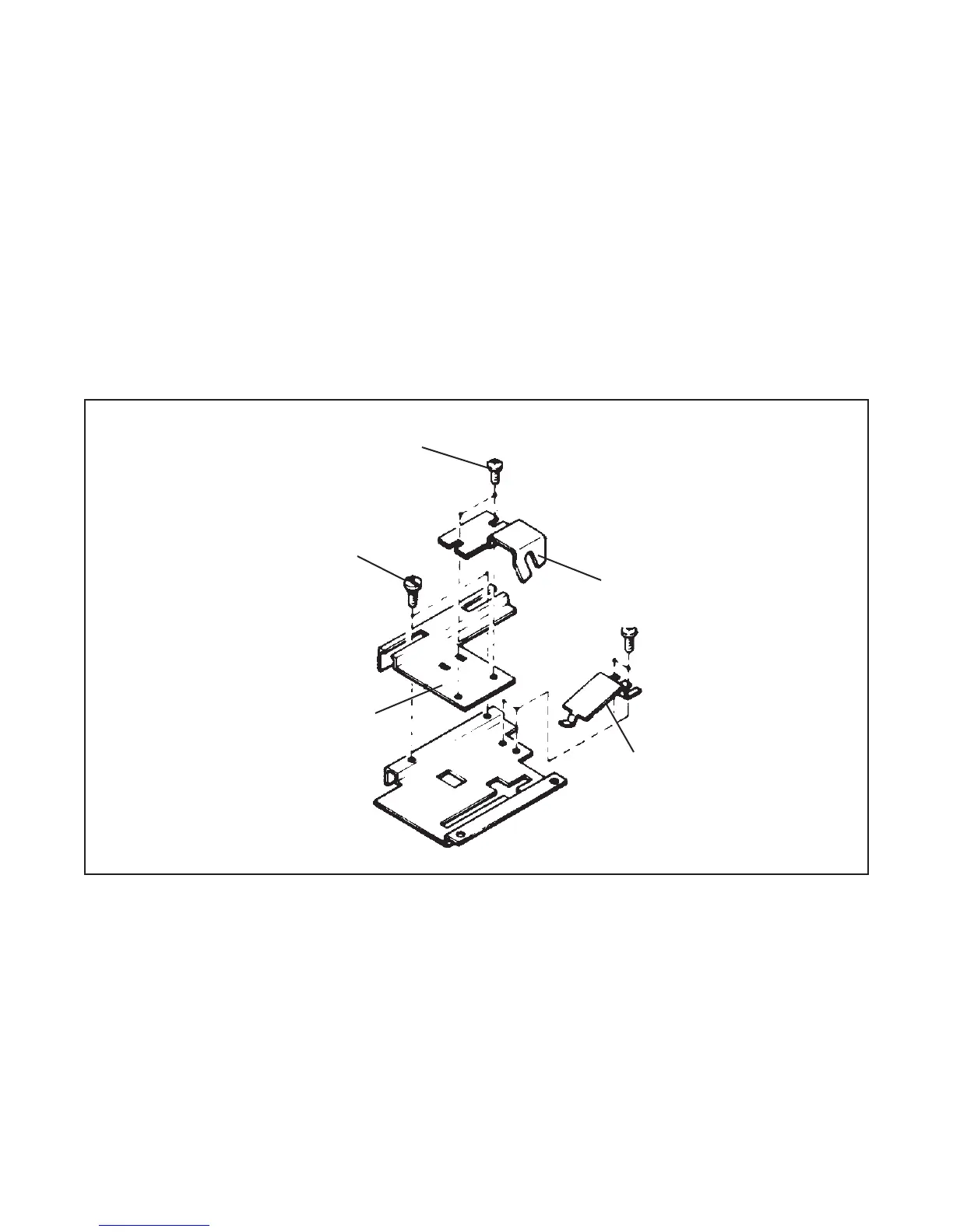
The assembly relationship of the parts of the viewfinder selector is shown in Figure 4-17. The
position of the detent spring affects the position of the lens number (127 or 150) shown at the
viewfinder indicator.
The position of the metal mask driver affects the position of the metal mask as it blanks or reveals
the framing image.
Note: Perform aiming and framing tests and adjustment after reassembly.
Figure 4-17. Parts of the viewfinder selector
Removing Covers from Rangefinder Assembly (Model 600SE Only) (Figure 4-18)
Pry plate from eyepiece assembly area. Remove single screw, shown in Figure 4-18. Use
tweezers to gently loosen sponge filler from eyepiece assembly area. Lift cover from rangefinder.
Remove sponge from cover by gently peeling it from adhesive.
Phillips Head Screw
Metal Mask Driver
Guide Screw
Detent Slot
Detent Spring
 Loading...