79
5. If the base lines do not line up, remove rangefinder top cover and make any necessary topside
adjustment (Figure 5-4). If necessary, use trichloroethylene to free topside adjusting screw.
Turn topside adjusting screw only. Observe movement of infinity-tube-target image through the
viewfinder eyepiece. Adjust until base lines line up as shown in Figure 5-2. The base lines
must butt each other to be within allowable limits. Replace top cover.
Figure 5-4. Location of topside adjusting screw
Infinity Tube Tracking Test
1. Completing the topside the test Steps 1 through 5 prepares the RF/VF for this test.
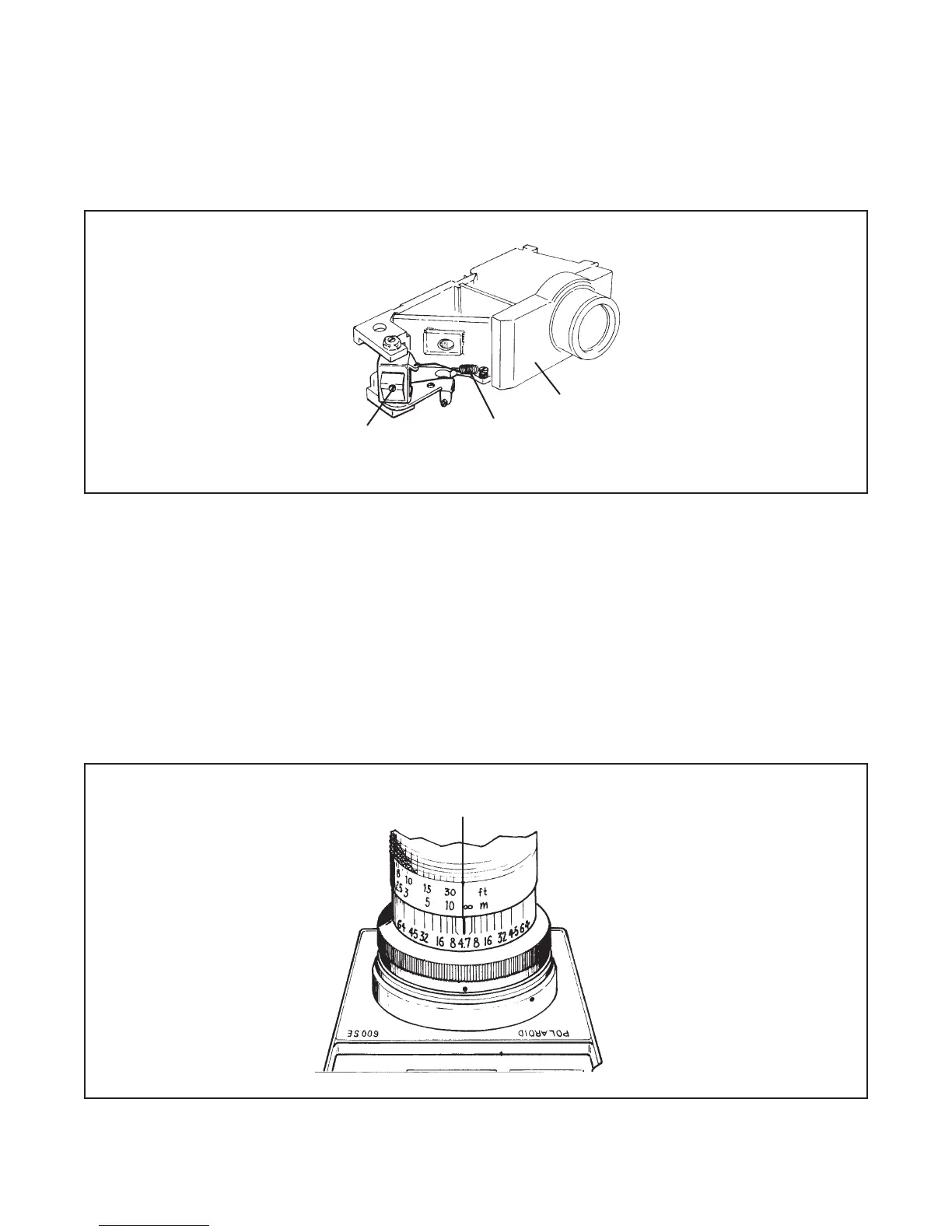
2. Sight through the RF/VF eyepiece. Focus to get perfect image coincidence. Mark with a
pencil the location of perfect image coincidence on the distance scale of each lens as shown
in Figure 5-5.
Figure 5-5. Marking image coincidence at infinity
Topside Adjusting Screw
Spring
Rangefinder
Image Coincidence
 Loading...