62
shutter assembly in a plastic bag.
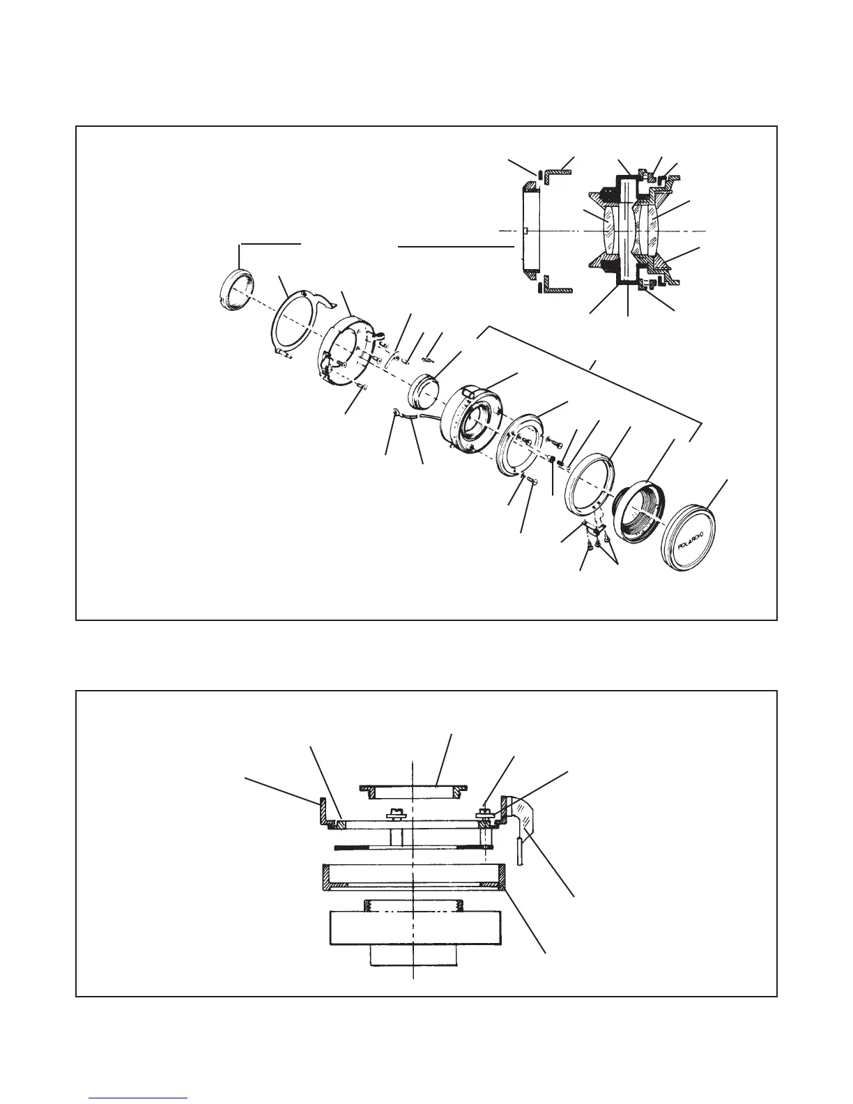
Figure 4-52. Disassembly of front end of 127MM and 150MM lens barrel
Figure 4-53. Removing speed mark ring
Disassembly of 127MM Lens Barrel
Key No. Part Name
1 Shutter release Ring
2 Shutter Cover Assembly
3 Earth Plate
4 Screw
5 Spring
6 Lens assembly, Rear
7 Seiko Shutter
8 Index Mark Ring
9 Click Spring Holder
10 Spring
11 Steel Ball
12 Aperture Ring #17
13 Lens Assembly, Front
14 Lens Cap
15 Screw
16 Screw
17 Aperture Control Knob
18 Screw
19 Washer
2 0 Tube
21 Contact Lug
1
2
3
4
5
6
7
8
9
10
11
12
13
14
15
16
17
18
19
20
21
4
Retaining Nut
1
2
7
8
12
Aperture Blades
Shutter Blades
Front Lens Lock
Ring
Time Mark Ring
Cross Section of Front
End of Lens Barrel
13
Note: Collimation of lens will be required after any
disassembly of lens system.
Front End of Lens Barrel
(6 through 13)
Aperture
Ring
Index Mark
Ring
Spanner Nut
Screws (3)
Retaining
Washers (3)
Aperture
Control Knob
Speed Ring
 Loading...