Chapter 5 Function parameter
137
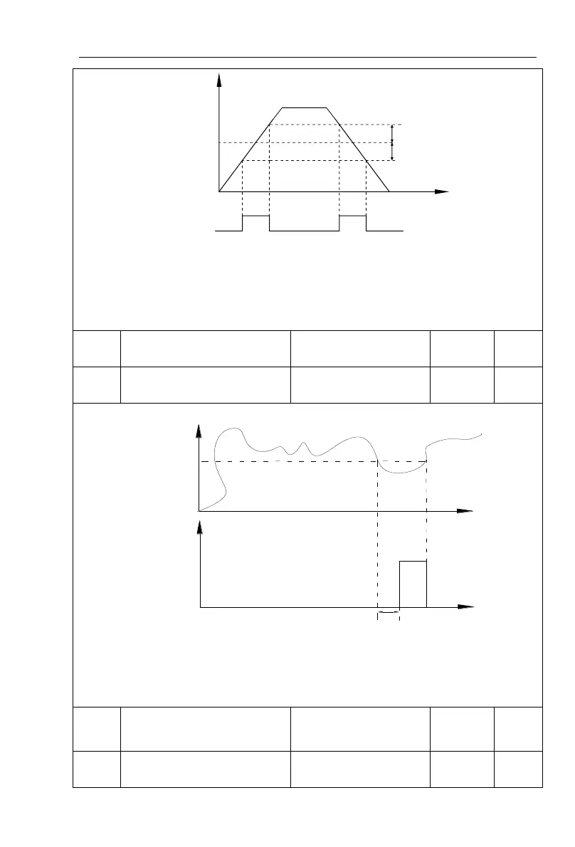
When the inverter's output frequency randomly reaches the range of the detected
value(positive or negative), the multi-function DO will output ON signal.
PI9000 provides two groups of parameter to set frequency value and frequency
detection range. The above figure is the schematic diagram of the function.
Zero current detection level
0.0% to 300.0% (rated
motor current)
Zero current detection delay
time
Zero current
detection level
F7.32
Time t
Output
F7.33
Zero current detection delay time
Time t
Zero current
detection signal
ON
When the inverter's output current is less than or equal to zero current detection level
and lasts for longer than the delay time of zero-current detection, the inverter's multifunction
DO will output ON signal. The figure is the schematic diagram of zero current detection.
Overrun value of output
current
0.0% (not detected)
0.1% to 300.0% (rated
motor current)
Output Current overrun
detection delay time
Random arrivals frequency
Random arrivals frequency
detection signal DO or
relay
Frequency detection range
Schematic diagram of random arrivals frequency detection
 Loading...

