Device Manual CANlink wireless
Functionality and features
PROEMION GmbH | Phone: +49 661 9490-600 | Fax: +49 661 9490-666 | info@proemion.com | proemion.com | Version 1.0 24
© 2016RM MICHAELIDES● VX.X ● Device Manual CANlink 5000 series © 2016RM MICHAELIDES● VX.X ● Device Manual CANlink 5000 series © 2016 PROEMION GMBH > 1.0 EN > Device Manual CANlink wireless 3000 series
3.2 Connectors
The device features the following connectors:
> 1x CAN / power connector
> 1x RS232 connector
> 1x RF antenna connector (only model variant 3002)
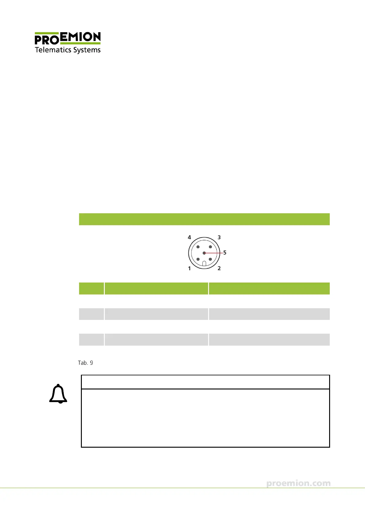
3.2.1 CAN / power connector
Use the CAN / power connector to connect the device to the CAN bus and supply it with
power. For the pin assignment of the CAN connector, see the following overview.
CAN/power connector
Pin Designation Description
1 Ground Power supply / reference ground
2 VCC (8-32 V
DC
) Power supply
3 Terminal 15 (digital input) Terminal 15 / Ignition I/O
4 CAN-High CAN
5 CAN-Low CAN
Connector assignment CAN / power connector
INFORMATION
Connect pin 3 (terminal 15) to VCC if you do not want to use sleep mode.
If you leave pin 3 unoccupied, the device may not start, or it may get stuck in sleep mode.
Use the CAN cable M12 5-pin/D-Sub/Power terminal 15 ON from the starter kit for
configuration and testing. In this cable, VCC is already Bridged with terminal 15.
If the device remains in sleep mode after switching on the power supply, it will awake upon
receipt of a CAN message.