Device Manual CANlink wireless
Getting started
PROEMION GmbH | Phone: +49 661 9490-600 | Fax: +49 661 9490-666 | info@proemion.com | proemion.com | Version 1.0 37
© 2016RM MICHAELIDES● VX.X ● Device Manual CANlink 5000 series © 2016RM MICHAELIDES● VX.X ● Device Manual CANlink 5000 series © 2016 PROEMION GMBH > 1.0 EN > Device Manual CANlink wireless 3000 series
4.2.2 CAN
Connect the device interfaces to the CAN bus whose data you want to log or send. For test
purposes, connect the device to a PC using a communication gateway (e.g. CANview USB).
The CAN connection terminal CAN-High and CAN-Low signals must match the signals of the
connector on the device. You can connect Ground of the supply connector with CAN-GND
because there is no galvanic isolation.
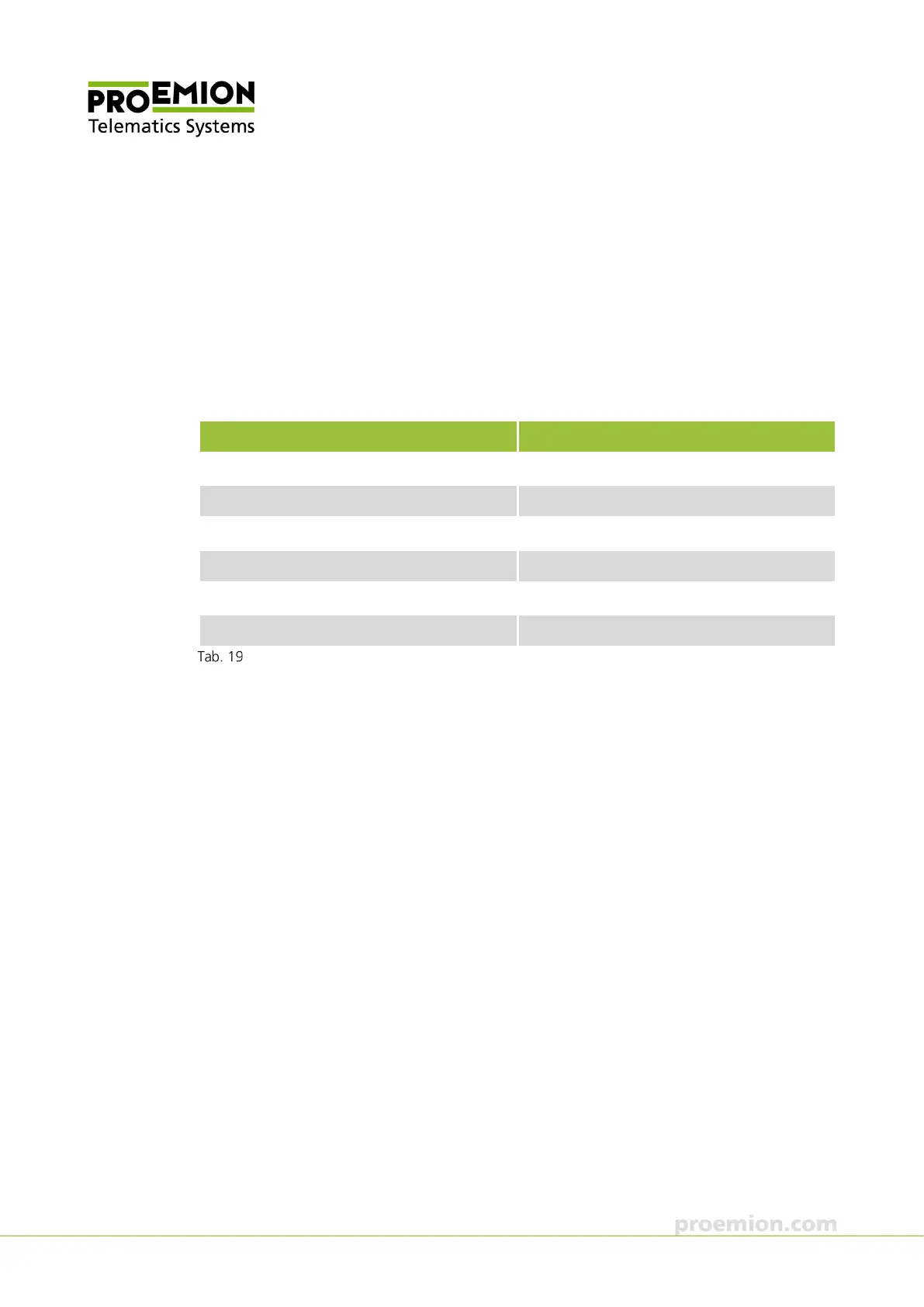
The following table provides an overview of the CAN bit rates in relation to the bus length:
CAN bit rate Maximum bus length
1 mbit/s 25 m
800 kbit/s 50 m
500 kbit/s 100 m
250 kbit/s 250 m
125 kbit/s 500 m
50 kbit/s 1000 m
CAN bit rates
4.2.3 CAN bus termination
In any bus system, signal reflections at the end of a wire or cable can cause interference which
can in turn cause transmission errors. To minimize these reflections, place a terminator at each
end of transmission lines. The terminating resistance between CAN-High and CAN-Low must
match the characteristic impedence of the transmission cables. In CAN bus networks, normally
unshielded, twisted cable pairs are used for signal transmission. The characteristic impedance of
the transmission lines is roughly 120 Ω. The terminator between CAN-High and CAN-Low must
be 120 Ω.