Device Manual CANlink wireless
Functionality and features
PROEMION GmbH | Phone: +49 661 9490-600 | Fax: +49 661 9490-666 | info@proemion.com | proemion.com | Version 1.0 25
© 2016RM MICHAELIDES● VX.X ● Device Manual CANlink 5000 series © 2016RM MICHAELIDES● VX.X ● Device Manual CANlink 5000 series © 2016 PROEMION GMBH > 1.0 EN > Device Manual CANlink wireless 3000 series
3.2.2 RS232 connector
Use the RS232 connector to connect the device to a PC. Configuration and firmware updates
are transferred to the device via the RS232 connector. You can find instructions on loading
firmware updates in chapter Firmware update. For the pin assignment of the RS232 connector,
see the following overview.
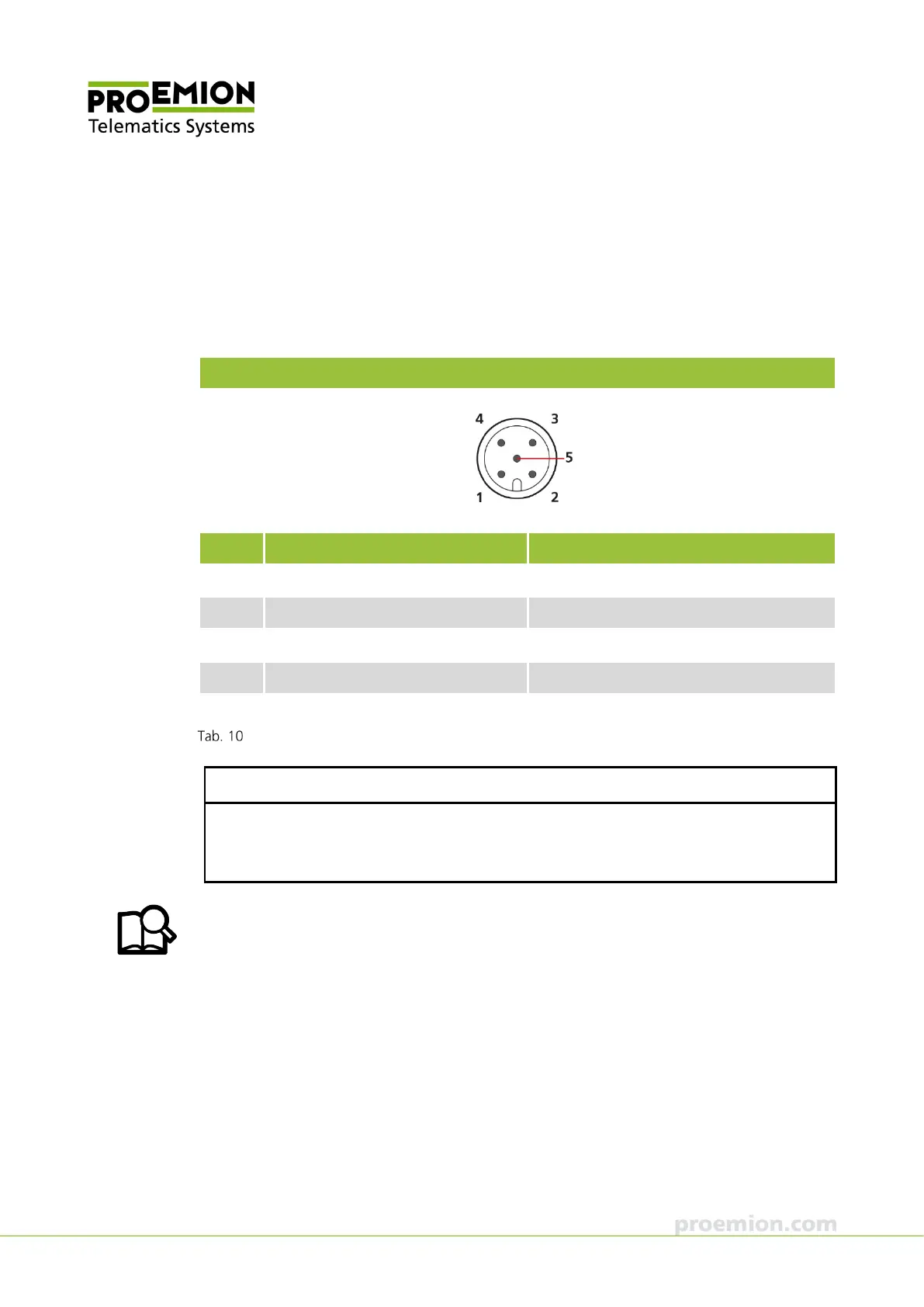
RS232 connector
Pin Designation Description
1 Ground Power supply / reference ground
2 - -
3 BOOT (DSR) Input, BOOT pin (data set ready)
4 RXD RS-232 receive (input)
5 TXD RS-232 transmit (output)
Connector assignment of RS232 connector
NOTICE
Only use pin 3 to activate boot mode. Connect pin 3 to the DTR pole of the RS232 Interface
of the PC to activate boot mode. The PROEMION software automatically controls this signal.
In normal operation, this connector must not be occupied.
You can find information on configuration files and CANlink wireless Configurator in
chapters Configuring the CAN-Bluetooth Interface, Configuring a CAN-WLAN Interface, and
CANlink wireless Configurator.