Device Manual CANlink wireless
Functionality and features
PROEMION GmbH | Phone: +49 661 9490-600 | Fax: +49 661 9490-666 | info@proemion.com | proemion.com | Version 1.0 29
© 2016RM MICHAELIDES● VX.X ● Device Manual CANlink 5000 series © 2016RM MICHAELIDES● VX.X ● Device Manual CANlink 5000 series © 2016 PROEMION GMBH > 1.0 EN > Device Manual CANlink wireless 3000 series
3.4 Cable
3.4.1 CAN/power connector
The CAN cable M12 5-pin/D-Sub/Power terminal 15 ON (part number 136 000 187) has the
following connectors:
> 1x M12 5-pin female
> 1x D-sub 9-pin female
> 1x power connector
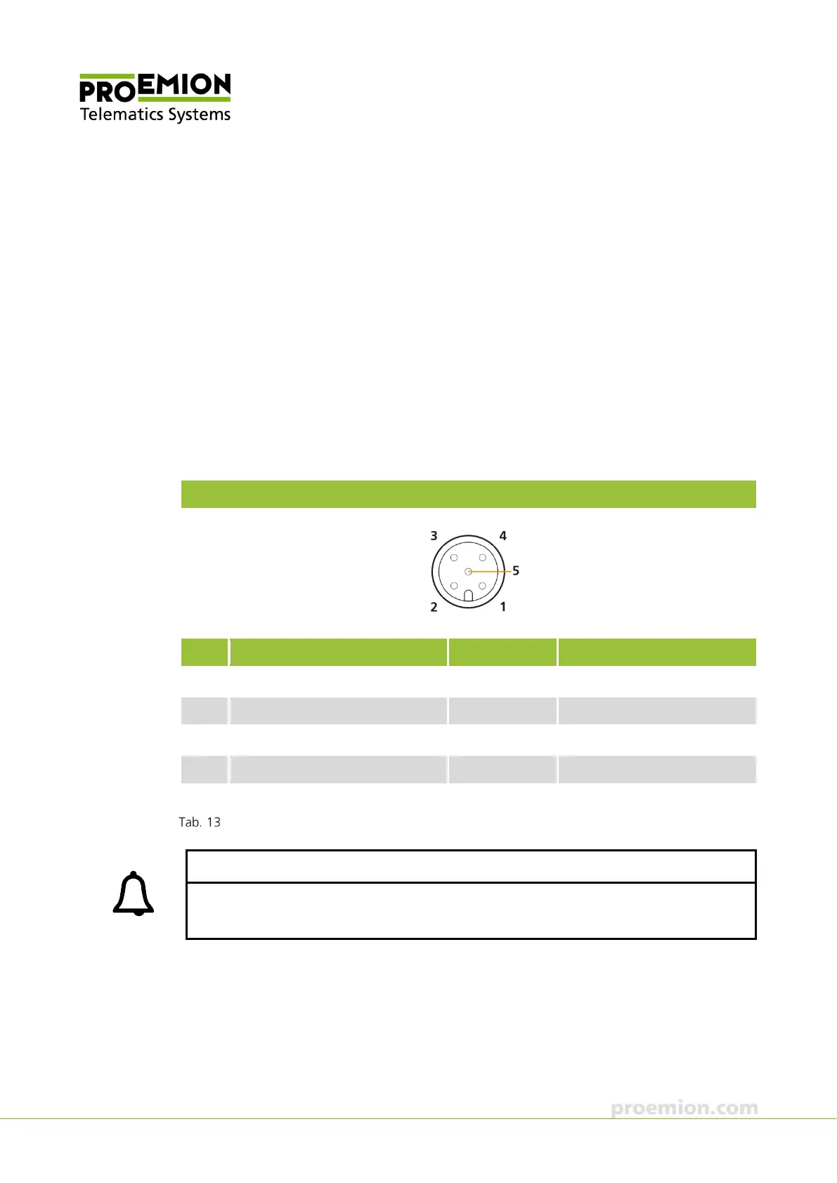
M12 5-pin connector, female
Pin Designation Color Description
1 Ground (-) Brown Power supply
2 VCC / terminal 30 (+) White Power supply
3 Terminal 15 / digital input Blue Input
4 CAN-High Black CAN
5 CAN-Low Gray, green CAN
CAN cable M12 5-pin/D-Sub/Power terminal 15 ON, M12 connector
INFORMATION
The color assignment applies to the cable CAN cable M12 5-pin/open 2M (part number 136
000 005).