Device Manual CANlink wireless
Getting started
PROEMION GmbH | Phone: +49 661 9490-600 | Fax: +49 661 9490-666 | info@proemion.com | proemion.com | Version 1.0 71
© 2016RM MICHAELIDES● VX.X ● Device Manual CANlink 5000 series © 2016RM MICHAELIDES● VX.X ● Device Manual CANlink 5000 series © 2016 PROEMION GMBH > 1.0 EN > Device Manual CANlink wireless 3000 series
4.5.2 Performing a function test of the CAN-WLAN Interface
It is advisable to perform a function test before using the device. In order to do so, you can
simulate the CAN bus with the aid of a communication gateway (e.g. CANview USB) and read it
out with RM CAN-Device Monitor.
NOTICE
In this section, a function test with the aid of a CANview USB is described. However, you
can also perform the test with comparable communication gateways. If third party
software is used, equivalent steps to create a test transmit-message must be performed.
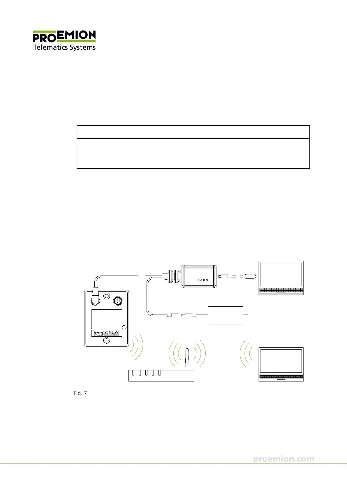
1. Connect the CANview USB to the PC with a USB cable.
2. Connect the CAN bus termination D-Sub/D-Sub CANterm 120 with the 9-pin Male
D-Sub Connector of the CANview USB.
3. Connect the CANlink wireless with the CAN cable M12 5-pin/D-Sub/Power terminal
15 ON to the CANview USB.
4. Connect the low-voltage coupling 1.3/3.5 of the CAN cable M12 5-pin/D-Sub/Power
terminal 15 ON to the country-specific power supply unit from the starter kit.
Connecting the CANlink wireless 3002 with a CANview USB to the PC