Device Manual CANlink wireless
Getting started
PROEMION GmbH | Phone: +49 661 9490-600 | Fax: +49 661 9490-666 | info@proemion.com | proemion.com | Version 1.0 61
© 2016RM MICHAELIDES● VX.X ● Device Manual CANlink 5000 series © 2016RM MICHAELIDES● VX.X ● Device Manual CANlink 5000 series © 2016 PROEMION GMBH > 1.0 EN > Device Manual CANlink wireless 3000 series
4.4.2 Performing a function test of the CAN-CAN-Bluetooth Bridge
It is advisable to perform a function test before using the device. In order to do so, you can
simulate the CAN bus with the aid of a communication gateway (e.g. CANview USB) and read it
out with RM CAN-Device Monitor.
NOTICE
In this section, a function test with the aid of two CANview USB is described. However,
you can also perform the test with comparable communication gateways. If third party
software is used, equivalent steps to create a test transmit-message must be performed.
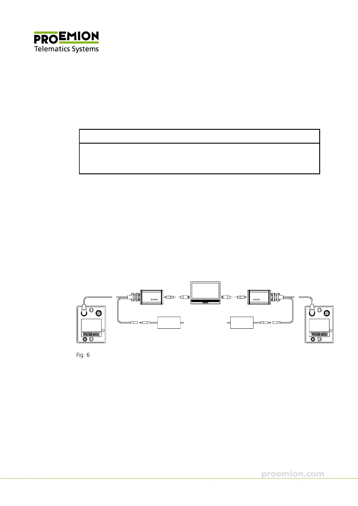
1. Connect the CANview USB to the PC with a USB cable.
2. Connect the CAN bus termination D-Sub/D-Sub CANterm 120 with the 9-pin Male
D-Sub Connector of the CANview USB.
3. Connect the CANlink wireless with the CAN cable M12 5-pin/D-Sub/Power terminal
15 ON to the CANview USB.
4. Connect the low-voltage coupling 1.3/3.5 of the CAN cable M12 5-pin/D-Sub/Power
terminal 15 ON to the country-specific power supply unit from the starter kit.
5. Repeat this procedure for the second CANlink wireless.
Connecting two CANlink wireless 3002 with two CANview USBs to the PC