Diagnostics and Troubleshooting RLX2 Series ♦ 802.11a, b, g, n
User Manual Industrial Hotspot
Page 46 of 161 ProSoft Technology, Inc.
May 8, 2013
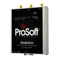
5.3 LED display
The RLX2 radio frontpanelincludesasetofLEDsthatindicatetheradio’s
status:
While booting up
When fully operational
This bi-color LED comes up amber when power is first applied. After power is
applied, this LED will go out completely for about four seconds while internal
hardware is initialized. After initialization, the power LED comes on green,
indicating the radio is fully operational.
While transmitting data over the wireless interface
While receiving data over the wireless interface
When serial data is received
When Ethernet data is being transferred over the wireless interface
Note that the state of the front-panel ETHERNET LED may not necessarily
correspond to the state of the DATA LED on the Ethernet connector. The DATA
LED indicates any traffic over the wired link, while the ETHERNET LED indicates
network data that will be sent (or has been received from) the wireless link.
For example if the radio is pinged over the wired link, the DATA LED will blink
but the ETHERNET LED will not (because the ping packet was not transmitted
over the air)
Blinks if SD card with new configuration inserted
Reserved for future additional use.
Blinks if SD card with new configuration inserted
Reserved for future additional use.
Blinks if SD card inserted with new configuration
This is for all radio modes.
Radios in Master mode:
No radios linked
One or more radios linked (right LED blinking).
DFS Channel Availability Check in progress (all LEDs blinking
Amber)
Radios in Repeater or Client mode:
No Signal
Radio linked, Poor Signal
Radio linked, Fair Signal
Radio linked, Good Signal
Once the power cable and Ethernet cable are connected to the radio, the
Power/Status LED should illuminate green. The SPEED LED should indicate a
valid wired link. The RF Transmit and RF Receive LEDs should start to blink
occasionally.