Do you have a question about the Proyecson PAA20+ and is the answer not in the manual?
General safety precautions and warnings for device installation and operation.
Detailed instructions and requirements for the safe and compliant installation of the device.
Guidelines and precautions for the correct and safe operation of the device.
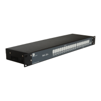
Details on the front panel components like LED indicators and test buttons.
Information on rear panel connectors including inputs, outputs, serial, and network ports.
Explanation of front panel indicators (24VDC, 3.3VDC, Activity) and manual control buttons.
Description of the reset button accessible through a pinhole.
Overview of rear panel connectors: power, inputs, outputs, network, serial, auxiliary power.
Instructions for connecting the PAA20+ to Dolby DSS servers via RS232.
Procedures for connecting PAA20+ to Doremi DCP servers via Ethernet and serial.
Procedures for connecting PAA20+ to GDC servers via Ethernet and serial.
Procedure for connecting PAA20+ to Qube XP-D servers via serial port.
Instructions for connecting PAA20+ to Datasat DC20 servers via serial port.
Procedure for connecting PAA20+ to Barco Alchemy (ICMP) servers via Ethernet.
Guide for connecting PAA20+ to Doremi, Dolby, or NEC IMS servers via Ethernet.
Instructions for connecting PAA20+ to Christie IMB S2 servers via Ethernet.
Steps to connect to the PAA20+ via Ethernet using a web browser.
Overview of the PAA20+ web administration interface and its sections.
Description of the Status page in the web interface.
Accessing advanced administration features requiring authentication.
Details on using the Remote Control page to manage outputs and inputs.
Configuration of the PAA20+ TCP/IP settings via the web interface.
Setting up automation messages and relay performance for outputs.
Configuration of messages sent to the server when inputs are activated.
Configuration of special features like Input Links and Startup State.
Information regarding the firmware update process for technical use.
Steps to configure Dolby DSS servers for operation with the PAA20+.
Setup procedures for Doremi DCP and Show Vault servers.
Adding PAA20+ as an Ethernet device in Doremi DCP and SV servers.
Adding PAA20+ as a serial device in Doremi DCP and SV servers.
Setting up output cues using the non-XML library method in Doremi servers.
Setting up output cues using the XML library method in Doremi servers.
Setting up input cues using the PAA20+ XML library in Doremi servers.
Setup procedures for Doremi, Dolby, and NEC IMS series servers.
Adding PAA20+ as an Ethernet device to Doremi, NEC, and Dolby IMS servers.
Setting up output cues for IMS servers using the non-library method.
Setting up output cues for IMS servers using XML library.
Setting up input cues for IMS servers using XML library.
Setup procedures for Barco Alchemy ICMP servers.
Adding PAA20+ as an Ethernet device in Barco Alchemy ICMP servers.
Setting up output cues for the Barco Alchemy server.
Setting up output cues for Barco Alchemy ICMP servers using XML library.
Setting up PAA20+ inputs for Barco Alchemy ICMP servers.
Setup procedures for GDC servers.
Adding PAA20+ as an Ethernet device to GDC servers.
Setup procedures for Qube servers.
Adding PAA20+ as a serial device to Qube servers.
Configuring Qube inputs on the PAA20+ for Play, Pause, Stop control.
Information on Datasat DC20 server setup, with details to follow.
Setup procedures for Christie IMB S2 servers.
Configuring Christie IMB S2 automation for the PAA20+.
Details on the pinout and circuitry of the Output 1 connector.
Details on the pinout and circuitry of the Output 2 connector.
Details on the pinout and circuitry of the Output 3 connector.
Details on the pinout and circuitry of the Input connector.
Examples of connecting digital inputs to the PAA20+.
Example connection for inputs with a negative common.
Example connection for inputs with a positive common.
Pinout diagram and function list for the serial port connector.
Hardware requirements for the Tester and Programmer software.
Installation instructions for the Tester and Programmer software.
Usage overview of the Tester and Programmer software.
Feature for detecting the PAA20+ on the network.
Functionality to test input/output operations of the PAA20+.
Information on programming the PAA20+ firmware (for certified personnel).
Abstract overview of the PAA20+ firmware composition.
Tools and files required for firmware programming.