MP3-PL Therapy Beam Analyzer T41050
Operating Manual – Assembly of the System
1 Bracket of the chamber cable holding device
2 Screw M5x10 (16x)
3 Base plate of the chamber cable holding device
4 Slider of the guide (4x)
5 Screw M6x25 and washer (4x)
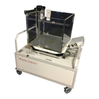
6 Perspex tank
7 Nipple for water connection at Perspex tank
8 Positioning device
9 Triangle holder of SCANLIFT
10 Screw M6x16 and washer (3x)
11 Water hose of SCANLIFT
12 SCANLIFT carriage and reservoir
2.2 Assembling the Junction
Box and the Moving
Mechanism
refer to Figure 8 up to Figure 10
Mount the junction box (T41013.1.100) on the
Perspex tank as shown in Figure 4, using M4x40
screws and washers.
Place the A-axis (5) on the supports (3) to the
right and left of the angle pieces (4) on the Per-
spex tank and secure the axis with a swivel
washer and an M6x16 screw (1) at each end, as
shown in Figure 8.
Hook the B-axis (5) onto the conical bolt of the
A-slide (3), at the same time guiding the sup-
porting rolls (7) over the support profile (6) at the
bottom of the Perspex tank, as shown in Fig-
ure 9.
Mount the B-axis on the A-slider, using two
M5x16 screws (2). Do not yet tighten the
screws.
Align the B-axis vertically. To do so, use one
edge of guide rail B and the vertical crosshair
line of the Perspex tank. Now tighten the two
M5x16 screws (2).
Remove the M3x12 screws (8) to loosen the
cable holder at the top and back of the A-slider.
Secure the two motor cables B/C (10) with the
cable holders (9) and tighten the two M3x12
screws (Figure 9).
Place the C-axis (4) on the B-slider (6), the cen-
tering shoulder (8) engaging in the centering
bore (7) and the catch pin (1) in the groove (2)
(Figure 10).