MP3-PL Therapy Beam Analyzer T41050
Operating Manual – Installation of the System for Measurement
3.3 Connecting the Detectors
3.3.1 24 PinPoint Chambers Type 31015 with
Chamber Cable Holding Device
T20015.1.200
Unsuitable laying and fixation of the chamber
cables.
Erroneous Measuring Position!
The chamber cables have to be fixed by suitable
laying and fixation in such a way that during
movement of the chambers the chamber cables
will not be exposed to tensile loading and thus
the moving mechanism will not be influenced.
Tensile load can deform the C-axis easily and
thus lead to erroneous measuring positions.
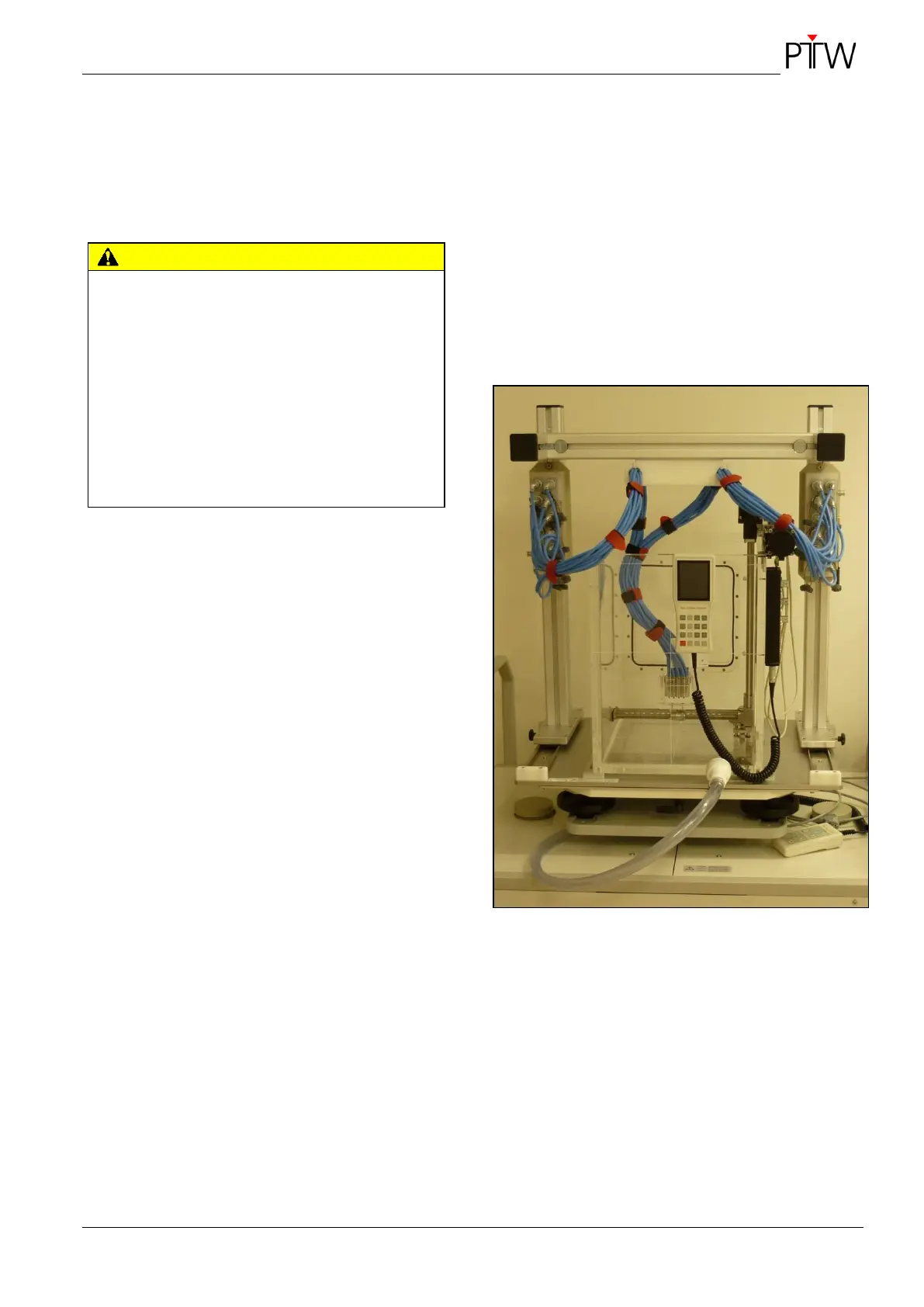
Mount the two detector connection boxes
T16007 onto the chamber cable holding device
according to Figure 19.
For this remove the appropriate screws
M6x20 and washers from the sliding blocks
at the chamber cable holding device.
Mount the detector connection boxes at the
topmost position of the chamber cable hold-
ing device in order to avoid the chamber ca-
bles catching the motors. For this fasten the
detector connection boxes on the sliding
blocks using the screws M6x20 and washers.
Connect twelve PinPoint chambers to each de-
tector connection box T16007 (sockets 1 up to
12).
Insert twelve chamber cables in each of the
appropriate openings of the cable holder accord-
ing to Figure 19.
Bundle the chamber cables with the supplied
Velcro strips as shown in Figure 19.
Connect one side of each connection cable
T26011 to a detector connection box
(MULTIDOS and HV sockets).
Connect the other side of each connection cable
T26011 to the MULTIDOS (rear side, detector
input labeled CHANNEL 1…12 and HV OUT
socket).
Figure 19: Laying and bundling of the chamber
cables