Configuration
R&S
®
TS7124M
95User Manual 1525.5394.02 ─ 05
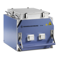
Figure 7-27: Inserting the half antenna ring into the chamber
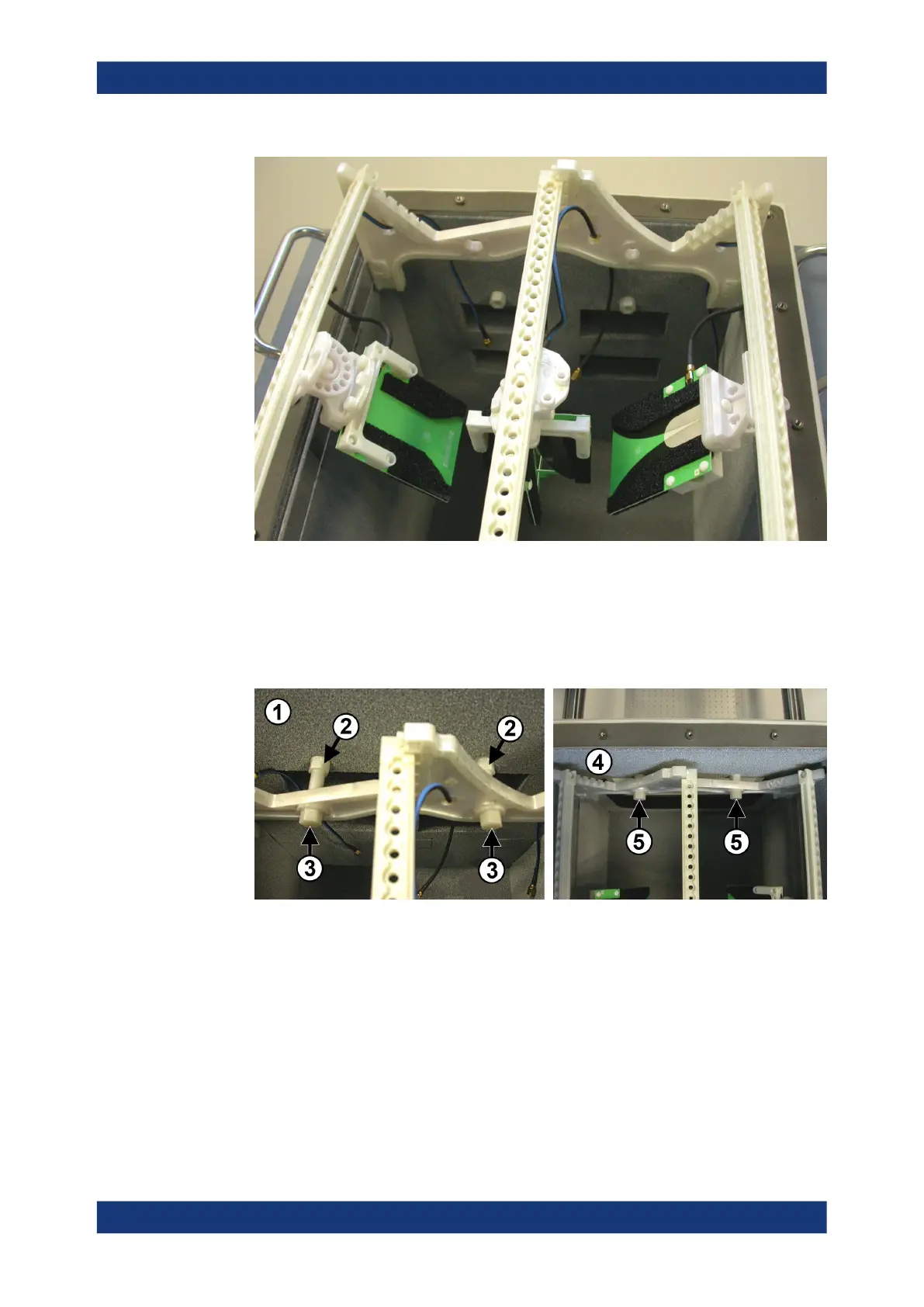
8. Fix the half antenna ring with the two long-distance bolts at the rear wall, and with
the two short-distance bolts at the front wall. The bolts are shown in Figure 7-23.
To screw the bolts into the spacers and tighten them, use a torque wrench No.13
with a torque of 2.8 Nm.
Figure 7-28: Left: fix two long bolts (3) at the rear wall inside the chamber. Right: fix two short
bolts (5) at the front wall
1 = Rear chamber wall
2 = Two spacers
3 = Two rear long-distance bolts
4 = Front chamber wall
5 = Two front short-distance bolts
9. Use an SMA wrench to attach the antenna cables to the SMA connectors at the
chamber's rear wall, minding the torque recommendation.
Make sure to make a note of the allocation of which antenna is connected to which
SMA connector.
Installing an antenna ring or holder
 Loading...