CHAPTER 4
48 SmarTrax™ Calibration & Operation Manual
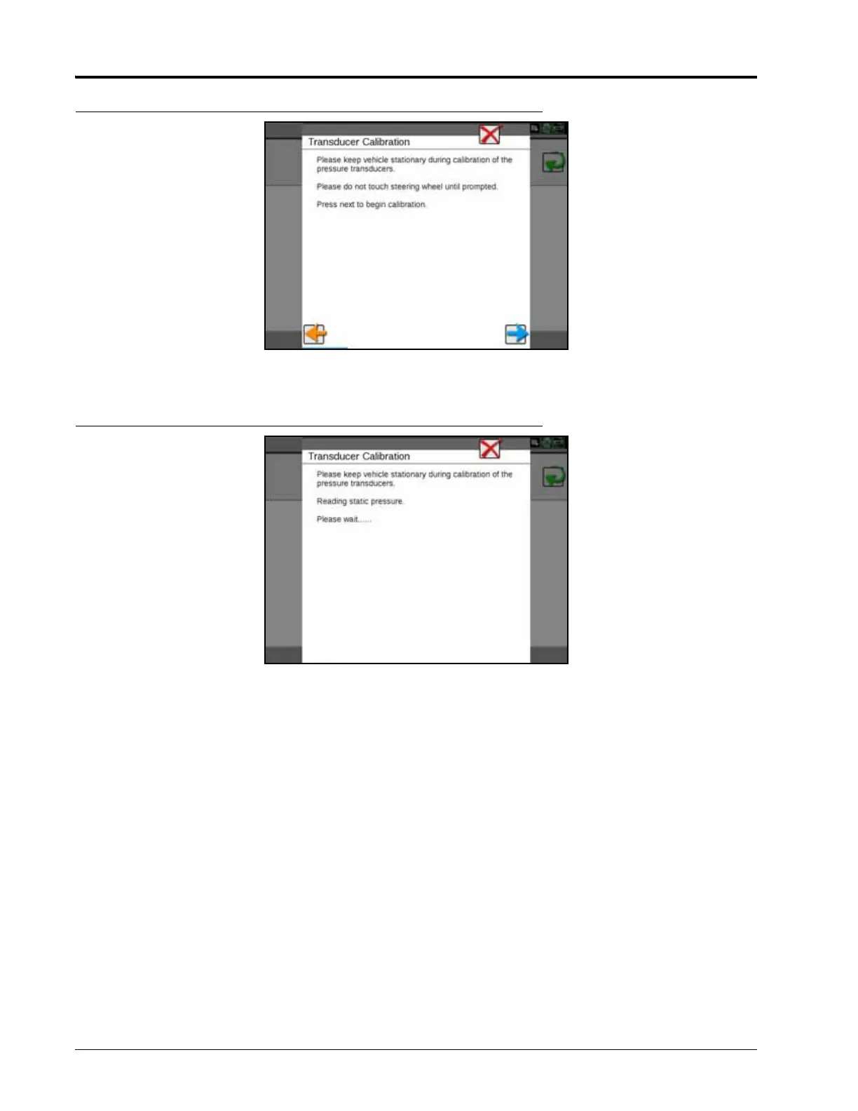
FIGURE 13. Transducer Calibrating Screen
1. Select Next. The following screen will appear:
FIGURE 14. Transducer Calibrating Screen
2. When prompted, turn the steering wheel 90° to allow the SmarTrax system to detect the hydraulic pressure
change. Once the system has detected the static and differential pressures, a screen displaying the steering
wheel status will appear.
NOTE: The steering wheel icon should appear green until the wheel is manually turned, at which point the
icon should turn red.
3. Verify the Viper 4 displays the correct steering operation.
NOTE: It may be necessary to increase the disengage setting to require more steering input to disengage
SmarTrax or to decrease the disengage setting to require less steering input.
4. If the system setting is correct, select Next.
5. Proceed Engage Switch and Node Orientation section on page 49 to continue with the SmarTrax system
calibration.