PG-FP5 CHAPTER 2 HARDWARE CONFIGURATION
R20UT0008EJ0400 Rev. 4.00 Page 24 of 240
Jul 15, 2010
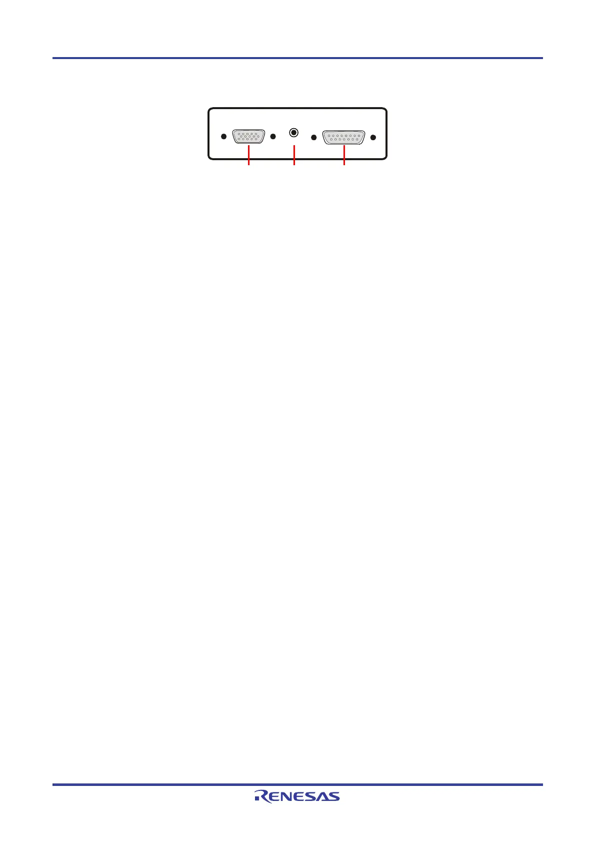
Figure 2-5. FP5 Target Connector Side
(1) Power supply connector
Connect the power supply connector to the AC adapter included with the FP5. For details on the power supply
connector specifications, refer to CHAPTER 9 CONNECTORS AND CABLES.
Caution Do not use an AC adapter other than that included with the FP5.
(2) Serial connector
Communication is established by using a serial cable (RS-232C cross cable) connection to connect the host
machine serial port and FP5 serial connector. The data transfer conditions are as follows.
• Data transfer speed: 9,600 bps, 19,200 bps, 38,400 bps, 57,600 bps, or 115,200 bps
• Data bit: 8 bits
• Parity: none
• Stop bit: 1 bit
• Flow control: hardware
The transfer speed is set to 9,600 bps by default, but it can be changed. For details on the serial connector
specifications, refer to CHAPTER 9 CONNECTORS AND CABLES.
(3) USB connector
Communication is established by using a USB cable to connect the host machine USB port and the FP5 USB
connector (mini-B type). This connector conforms with USB 2.0 standards. For details on the USB connector
specifications, refer to CHAPTER 9 CONNECTORS AND CABLES.
(4) Target connector
Connect the target connector to the target system using the target cable for on-board programming. Connect the
target connector to the program adapter using the target cable for off-board programming. For details on the target
connector specifications, refer to CHAPTER 9 CONNECTORS AND CABLES.
(5) GND connector
To reinforce the GND, connect the FP5 GND connector and the signal GND of the target system or program
adapter using a GND cable. For details on the GND connector specifications, refer to CHAPTER 9
CONNECTORS AND CABLES.
Caution The FP5 and target system may be damaged if the voltage between the FP5 GND and the target
system GND is different. Use the GND cable to match the voltage before connecting the target
cable.
(6) Remote connector
The FP5 can be remote controlled by connecting the remote connector and external control device. For details on
the Remote operation, refer to CHAPTER 7 USAGE THE REMOTE CONNECTOR, CHAPTER 9 CONNECTORS
AND CABLES.
Target connector
GND
connector
Remote
connector